Translations of this page?:
- Deutsch (de)
- English (en)
In an earlier article we could already see how a TRÅDFRI module can be removed from an IKEA lamp and used for your own LED projects. The module itself is used in various IKEA devices, including the lamps and drivers, as well as:
The function of the pins is then accordingly. Here is an overview:
| TRÅDFRI Pin | Lamp white | Lamp white spectrum | Power Plug | FYRTUR |
|---|---|---|---|---|
| PA0 | open | open | Button | Up Button |
| PA1 | open | VCC | NTC | LED |
| PA12 | - | PWM2 | Relay | TxD |
| PA13 | PWM | PWM1 | LED | RxD |
| PC10 | - | - | - | Down Button |
The module is controlled by an EFR32MG1PXXXF256 controller from Silicon Labs. He has a debug interface that is also available on the module. This is ARM's Serial Wire Debug (SWD) interface with 2 wires.
A debugger is required to be able to read or write to the FLASH. An inexpensive variant is again available from Ebay. You can find more information, among other things here.
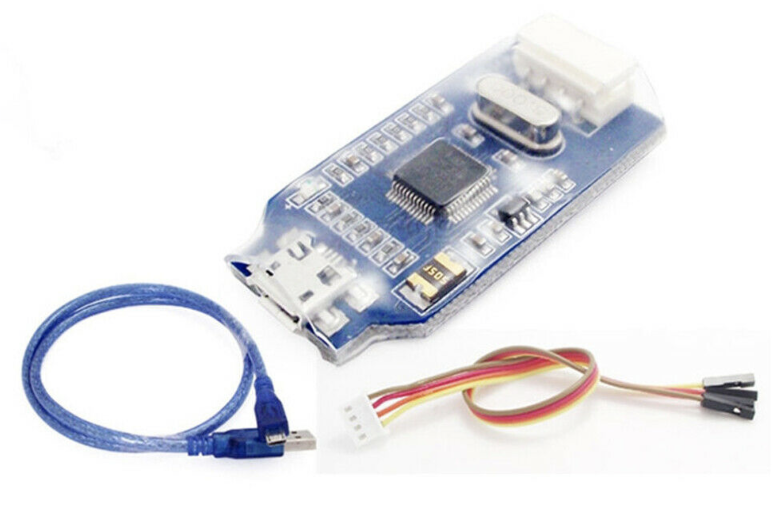
The 4 wires of the debugger are to connect to the module as follows:
| JLINK | TRÅDFRI Modul |
|---|---|
| VCC | VCC |
| SWDIO | PF1 |
| SWCLK | PF0 |
| GND | GND |
In addition, the module must be supplied with 3.3V. J-Link from SEGGER is available as software. Version V648b ran stable on my Mac.
In the terminal window we then enter the following command (adapt path):
<pfad>/JLinkExe -If SWD -Speed 5000 -Device EFR32MG1PXXXF256
The J-Link> prompt appears. To connect to the Cortex-M4 simply enter connect and if successful, the response looks like this:
J-Link>connect
Device "EFR32MG1PXXXF256" selected.

Found SWD-DP with ID 0x2BA01477
Found Cortex-M4 r0p1, Little endian.
FPUnit: 6 code (BP) slots and 2 literal slots
CoreSight components:
ROMTbl 0 @ E00FF000
ROMTbl 0 [0]: FFF0F000, CID: B105E00D, PID: 000BB00C SCS
ROMTbl 0 [1]: FFF02000, CID: B105E00D, PID: 003BB002 DWT
ROMTbl 0 [2]: FFF03000, CID: B105E00D, PID: 002BB003 FPB
ROMTbl 0 [3]: FFF01000, CID: B105E00D, PID: 003BB001 ITM
ROMTbl 0 [4]: FFF41000, CID: B105900D, PID: 003BB923 TPIU-Lite
Cortex-M4 identified.
The Cortex-M4 of the TRÅDFRI module has four FLASH areas that we have to consider:
| Area | ADDR | Size |
|---|---|---|
| MAIN | 0x0 | 0x40000 |
| USER | 0xfe00000 | 0x800 |
| LOCK | 0xfe04000 | 0x800 |
| CHIP | 0xfe08000 | 0x400 |
To read out and save, we enter the following commands:
J-Link>savebin TRADFRI_main.bin 0x0 0x40000
Opening binary file for writing... [/Users/rolf/Projekte/TradFri/TRADFRI_main.bin]
Reading 262144 bytes from addr 0x00000000 into file...O.K.

J-Link>savebin TRADFRI_chip.bin 0xfe08000 0x400
J-Link>savebin TRADFRI_lock.bin 0xfe04000 0x800
J-Link>savebin TRADFRI_user.bin 0xfe00000 0x800
With the command J-Link> verifybin TRADFRI_main.bin 0x0 the read out can be verified again.
Fortunately, all of the modules I read were not read-protected so far.
If we collect all four files, we can now reprogram any module and thus obtain the desired function. In my case I took the TRÅDFRI modules out of the repeater and converted them into blind modules and used them here.
Programming is just as easy as reading out with the following commands:
J-Link>loadbin TRADFRI_blind_main_2_2_009.bin 0x0
Downloading file [TRADFRI_blind_main_2_2_009]...Comparing flash   [100%] Done.
Erasing flash     [100%] Done.
Programming flash [100%] Done.
Verifying flash   [100%] Done.
J-Link: Flash download: Flash programming performed for 1 range (188416 bytes)
J-Link: Flash download: Total time needed: 6.193s (Prepare: 0.112s, Compare: 0.298s, Erase: 2.700s, Program: 2.931s, Verify: 0.143s, Restore: 0.007s)
O.K.

J-Link>loadbin TRADFRI_blind_chip.bin 0xfe08000
J-Link>loadbin TRADFRI_blind_lock.bin 0xfe04000
J-Link>loadbin TRADFRI_blind_user.bin 0xfe00000
The same procedure can also be used for other TRÅDFRI devices that do not use this module. The circuit structure is always the same. All you have to do is find the four connections on the circuit board. These are always available as pads for the module test and are therefore easily accessible.
For the blind project I converted the standard TRÅDFRI on/off switch into a button for the blind. Unfortunately, you can't buy one individually.
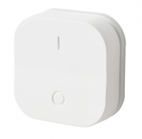

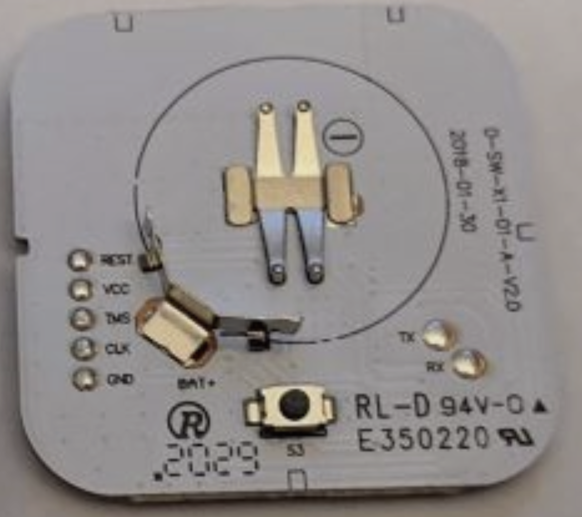
How to open the button is here well described. The connections for programming are labeled on the back of the PCB and the connection to the debugger is shown as follows:
| JLINK | TRÅDFRI Taster |
|---|---|
| VCC | VCC |
| SWDIO | TMS |
| SWCLK | CLK |
| GND | GND |
All TRÅDFRI components support Over-The-Air (OTA) updates. You don't need to worry about that, as it takes place in the background, for example through the gateway. However, if we want to flash the current firmware while reprogramming, we can also fetch the data directly from the IKEA OTA server. Resourceful developers have written a Python Script. With the help of this script, all files available on the server are downloaded. The example for the roller blind then looks like this: ``10037585-5.1-TRADFRI-connected-blind-2.2.009.ota.ota.signed''
However, only the MAIN area of the FLASH is updated. The USER, LOCK and CHIP areas do not change and are therefore not online either. If you want to reprogram a module with a different functionality, you have to read it out yourself at least once in order to get to the data for USER, LOCK and CHIP.
The loaded data is encapsulated in an exotic format with the abbreviation NGIS. Here again some work was necessary to decrypt the format and extract the binary file. The program Synalyze it! Per. The graph file is available in the download area.

For extracting I wrote a Python script that is also in the download area. In the previous tests, the extracted version was binary identical to the one that was read out.
If you like my articles feel to donate a cappuccino or so…
