User Tools
Sidebar
This is an old revision of the document!
Table of Contents
Bed Sensor
Motivation
Everyone who has become infected with the topic of smart home considers almost continuously how he/she can still automate manual, recurring tasks further. Provided that the appropriate sensors and actuators are already available. A sensor area that seems somewhat underrepresented is the occupancy sensor, e.g. to trigger or refrain from actions by going to bed.
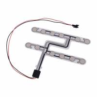
There are alarm mats as bed rugs or professional bed sensors from the care sector. The seat sensors from the automotive industry also perform a similar task. What they all have in common, however, is the lack of connection to an open protocol such as MQTT and of course the usually very high purchase costs.
Some resourceful developers have addressed this gap and have, for example, integrated switches into the bed frame Selbstgebauter Bettsensor... Steuern und Regeln im Schlaf!
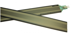
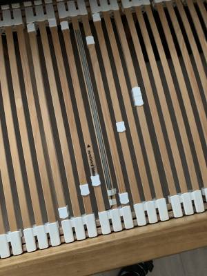
My approach looks a little different to be as minimally invasive as possible for the bedstead. I use a pressure-sensitive resistor (FSR) as a sensor. It is also available in an extra long version of 60cm FSR 408. When unloaded, the resistance is high ohm (> 10MOhm) and with a load of 10kg the value is reduced to a few 100 ohms. The sensor is self-adhesive and can be easily attached to a slatted frame, for example.
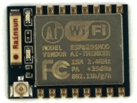
With the FSR 408, the existing pressure can easily be evaluated with a simple resistor network and an A/D converter or comparator. There are several options for getting the value into the smart home network. One of the simplest is an ESP8266 module (ESP-07) with the open-source firmware called ESP Easy. By the way, you can find a similar approach with a Raspberry Pi here.
Features
The solution for the occupancy sensor should meet the following requirements:
- Occupancy evaluation via pressure-sensitive resistor (e.g. FSR 408)
- Two sensor inputs for a double bed
- WiFi integration
- MQTT protocol
Hardware
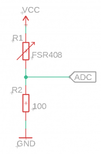
The resistor network for evaluating the pressure looks like this:
The output voltage to the ADC is calculated as follows:
V_ADC = Vcc ( R2 / (R2 + R1) )
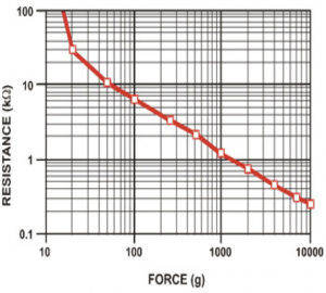
where Vcc = 3.3V. The corresponding voltage values for the support points of the force diagram are listed in the table:
| Force [kg] | FSR Resistance [KOhm] | V_ADC [V] | Digital Value [dec] |
|---|---|---|---|
| 0.1 | 6 | 0.05 | 51 |
| 0.5 | 2 | 0.16 | 164 |
| 1.0 | 1.2 | 0.25 | 256 |
| 2.0 | 0.75 | 0.39 | 399 |
| 4.0 | 0.45 | 0.60 | 614 |
| 7.0 | 0.30 | 0.83 | 849 |
| 10.0 | 0.25 | 0.94 | 962 |
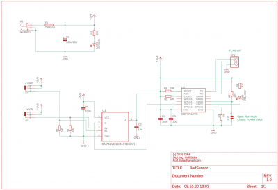
In our application, the maximum value should not exceed 1V, as the internal analog reference voltage of the ESP-07 is 1V. We also need a multiplexer to evaluate two sensors. The complete circuit diagram is still very simple.
Of course, you can also connect just one FSR408 with R2 directly to the module, possibly avoiding the circuit board with free wiring.
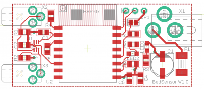
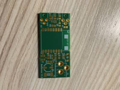
In order to keep the module as small as possible, the circuit is made in SMD. Suitable home soldering techniques have already been published in various places.
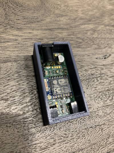
The sensors are connected via standard 2.5mm jack sockets (JY029). The power supply can also be plugged in with a 5.5 / 2.1mm hollow socket (HEBW21). You can find it very inexpensive Power Supplies with stabilized 3.3V DC voltage output. The bed sensor does not need more wired connectivity.
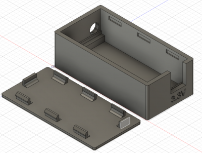
With a 3D printer an inconspicuous housing can be realized which can easily be attached with double-sided adhesive tape underneath the bed.
Programing
After the hardware has been created we still have to program the ESP module. As already mentioned, the bed sensor is based on ESPEasy. In the link you can also find instructions on how the ESPEasy firmware is installed on the module. In order to get into the programming mode, the jumper SJ1 must be closed during the reset release. The programming is done serially via JP1 (USB-serial converter).
Wenn alles geklappt hat und das Modul im heimischen WLAN eingebunden ist, kann die gesamte weitere Einstellung über das Webinterface erfolgen. Dazu benötigen wir:
- MQTT Controller setup
- Device Setup
- Rules Setup
MQTT Controller setup
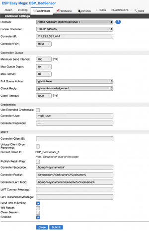
Der Bettsensor soll sich ja mit einem vorhandenen MQTT Server verbinden und die aktuelle Belegungsinformation bei Änderung dorthin übertragen. Dazu gehen wir auf den Reiter Controller und tragen die entsprechende Daten ein. Dazu gehören u.a. die IP Adresse des MQTT Servers sowie die Account Daten für die Anmeldung. Das Resultat sollte ähnlich dem folgenden Beispiel aussehen.
Devices
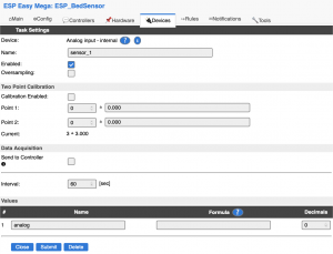
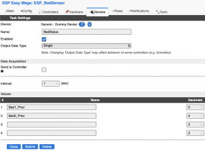
Als zweites brauchen wir ein Device was den analogen Wert misst und speichert. Das lässt sich über den Reiter Devices erreichen. Für jeden Sensor gibt es ein eigenes Device und zusätzlich benötigen wir noch ein Dummy Device um den vorherigen Messewert zwischen zu speichern.
Die grünen Zahlen rechts geben übrigens die aktuellen Messwerte wieder. In dem Beispiel liegt keiner im Bett.
Hier die Einstellungen für die Devices:
Rules
Nun haben wir eine Anbindung an den MQTT Server und wir können die Messwerte des ADC abfragen. Was fehlt ist die Ablaufsteuerung. Innerhalb des ESPEasy gibt es dafür die Rules: Dazu den folgenden Code in das Rules Set 1 kopieren.
On System#Boot do
  gpio,12,0
  TaskValueSet 3,1,100 	// default value at boot
  TaskValueSet 3,2,100 	// default value at boot
  timerSet,1,1
endon

On Rules#Timer=1 do
  TaskRun,1 	// Measure Bed 1
  GPIO,12,1
  TaskRun,2 	// Measure Bed 2
  GPIO,12,0

  if [sensor_1#analog] < 50 and [BedStatus#Bed1_Prev] > 49
    TaskValueSet 3,1,[sensor_1#analog]
    publish /home-assistant/%sysname%/sensor_1/analog,OUT
  endif

  if [sensor_1#analog] > 49 and [BedStatus#Bed1_Prev] < 50
    TaskValueSet 3,1,[sensor_1#analog]
    publish /home-assistant/%sysname%/sensor_1/analog,IN
  endif

  if [sensor_2#analog] < 50 and [BedStatus#Bed2_Prev] > 49
    TaskValueSet 3,2,[sensor_2#analog]
    publish /home-assistant/%sysname%/sensor_2/analog,OUT
  endif

  if [sensor_2#analog] > 49 and [BedStatus#Bed2_Prev] < 50
    TaskValueSet 3,2,[sensor_2#analog]
    publish /home-assistant/%sysname%/sensor_2/analog,IN
  endif

  TimerSet,1,1
endon
Während des SystemBoot setzen wir den Multiplexer entsprechend auf Eingang 1, die Startwerte auf 100 und einen Timer der jede Sekunde die folgende Routine aufruft. Jede Sekunde werden dann beide Werte ausgelesen und wenn es eine Veränderung um den Schwellwert gegeben hat, wird das Ergebnis an den MQTT Server gesendet. Das sind die Zustände IN bzw. OUT. Man kann natürlich auch die aktuellen Werte übermitteln und die Entscheidung ob IN oder OUT der Homeautomatisierung überlassen. Im folgenden Beispiel habe ich so mal eine Nacht aufgezeichnet.
Beispiel
Hier die Aufzeichnung der konvertierten Werte [0..1023] einer Nacht. Die Drops sind nicht bedingt durch eine altersbedingte Inkontinenz sondern das kurzzeitige Wegkuscheln auf die Bettmitte 
Fazit
Der Bettsensor läuft jetzt seit 2 Jahren ohne Probleme. Je nachdem wie stabil das heimische WLAN ist kann aber mal ein Neustart des Bettsensors notwendig werden.
Downloads
Links
- http://www.heise.de/hardware-hacks/artikel/SMD-Loeten-in-der-Pizzapfanne-1276166.html SMD Löten mit einfachen Mittel

