
Translations of this page?:
- Deutsch (de)
- English (en)
Our front door sits in the outer wall of our property and is therefore several meters away from the actual house. So far we've used a proprietary wireless doorbell solution, but with only one receiver unit. With an L-shaped bungalow there's no single spot for that receiver from which we can hear the bell everywhere.
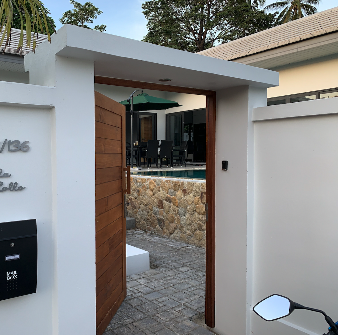
On top of that, Thai delivery services show up at very flexible times, so you can't always be on-site. A smart wireless doorbell was therefore a strong wish of mine. The requirements can be summarized as follows:
For this project I started the planning with the mechanics. Since I'll be walking past the new doorbell every day, the whole thing needs to look modern and nearly perfect so it doesn't annoy me every time I see it. Browsing the internet turned up a good number of DIY variants (here's a selection):
The one I liked best in terms of mechanical design was the variant from EI23 (along with the amusing video,  ).
).
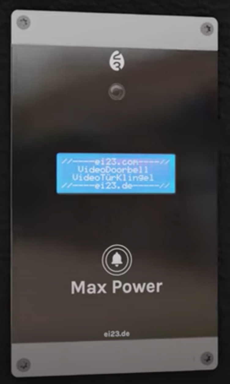
As mentioned, looks play an important role in this project, so I start the planning with the mechanics.
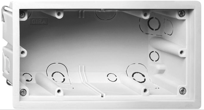
The basis for a secure installation is a suitable flush-mount box. I found one at GIRA. The E2 variant has just the right dimensions, allows the cover unit to be screwed on, and at around €3.50 is also affordable.
The control and viewing area will be glass, which we have cut to size by a local or online supplier:
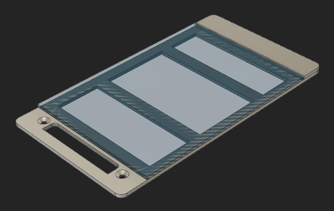
The cover frame is made from two layers of 2mm milled aluminum, or comes out of the 3D printer/laser cutter. Since I wanted the screws hidden, there are two parts. Below you can see the larger frame with the mounting holes, and above that the cover, which is actually held on magnetically. For that we glue a thin metal strip (e.g. from a staple strip) to the back. The magnets sit on the inner mount (see below).
To make use of the mounting holes, we modify the empty box slightly by replacing the 4 corner mounting screws with 12mm long M3 hex standoffs. These are secured from below with M3 screws, leaving the M3 threads available for the cover frame.
The glass pane gets a printed foil applied to the back, which you can design freely. It's:
 The final sticker is the same size as the glass, but the production process requires a 3mm margin.
You can create the design template to scale in any vector design tool of your choice (I use BoxySVG on macOS):
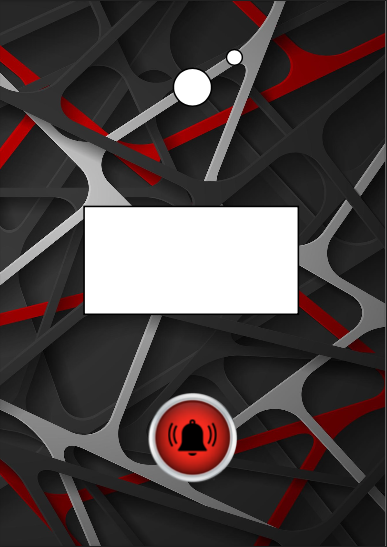
The foil must be ordered with full white backing print so it's also opaque, otherwise you'll see the frame skeleton underneath later.
Behind the red button is where the touch sensor will later sit; the rectangular cutout in the middle is for the display, and the holes at the top are for the camera and flashlight. Before applying the adhesive, the white areas still need to be cut out with a craft knife.
Once the foil arrives from the print shop, it's applied to the glass with a squeegee. The glass can then be fixed to the frame with a special glass adhesive or a suitable tape. I additionally sealed/bonded the gap between glass and frame with black acrylic.
The finished assembly meets my approval and motivates me to carry on…
A look at the requirements list shows four functional units that need to be implemented:
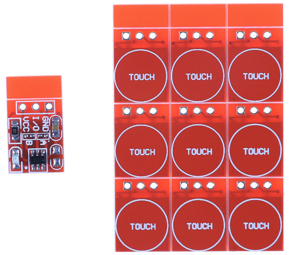
There are ready-made solutions that are entirely sufficient in our case. They mostly have a TTP223 chip onboard providing a capacitive sensor, with the sensor surface already on the PCB. The sensitivity is high enough to respond right through our glass pane. The output provides a digital signal for evaluation.
Because of the intense brightness here in Thailand, I avoid self-illuminating displays outdoors, even in shaded areas. That's what gave me the idea of using an e-paper display instead. There won't be rapid content changes, and readability (it also serves as the nameplate) is maintained even during a power outage. Here too there are ready-made solutions with a controller. The largest display that fits the housing is a 2.13 inch model from Waveshare.
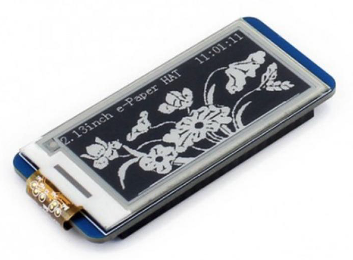
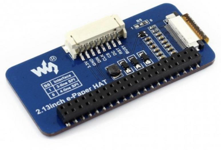
I went with the Raspberry Pi HAT variant, since its controller also has a cable connector, simplifying the wiring.
Here too a ready-made solution does the job. The ESP32 CAM module offers a compact camera. We swap the lens for a wide-angle (160°) one with a longer connecting cable. That reduces the blind spot and gives us more mechanical freedom to place the lens further away from the module.
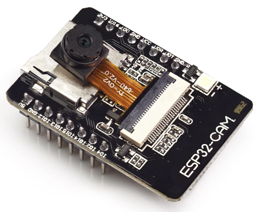
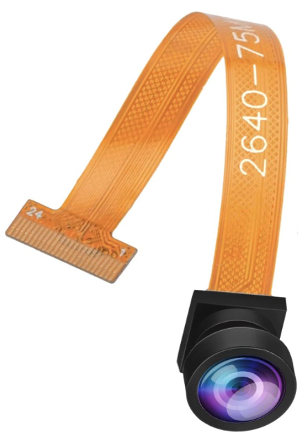
With this module we're also immediately on the home WiFi network and can use it to also control the other components, such as the touch button and sound.
One option for voice output is a synthetic solution, which would allow arbitrary text on the fly. But since the variety of text snippets needed here is manageable, I instead went the route of an MP3 player. The following compact module, the DFPlayer Mini, has everything we need:
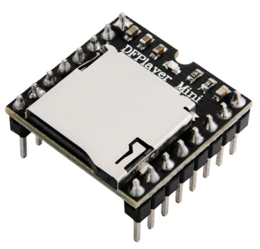
It's also addressable via a serial interface, has an SD card slot for stored sound files, and can drive a 3W speaker directly. No need to design anything of our own here. To be able to easily call up the saved MP3 files later, I set up the following structure on the SD card:
  /DoorBell.mp3	  Ding-Dong
  /01/ (English)
    001.mp3   Please wait. We will open the door.
    002.mp3   Please leave the parcel in front of the door.
    003.mp3   Please call the number shown on display. Thanks.
    004.mp3   Please wait a moment.
  /02/ (Thai)
    001.mp3   Please wait. We will open the door.
    002.mp3   Please leave the parcel in front of the door.
    003.mp3   Please call the number shown on display. Thanks.
    004.mp3   Please wait a moment.
If you don't want to immortalize your own voice there, professional voice recordings in various languages are also available. Worth a look here: text-to-speech.
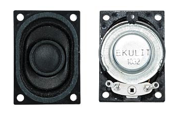
For the speaker I'd already used the compact small speaker LSM-S30K in other projects. It fits perfectly here too. Thanks to the resonance chamber of the empty housing, the sound is full and loud enough even through the glass pane. I keep the volume well below max.
Before wiring up all the modules, let's first take a look at the inner mechanics. The empty housing has a lower level, 12mm deeper, that we can use to fix both the front and the control modules. A few experiments led to the following mount:
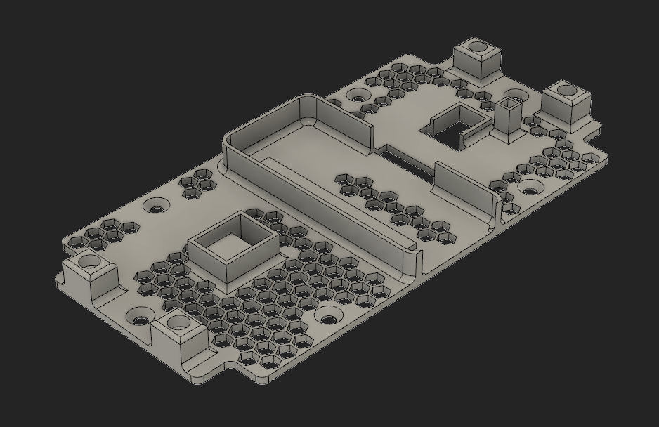
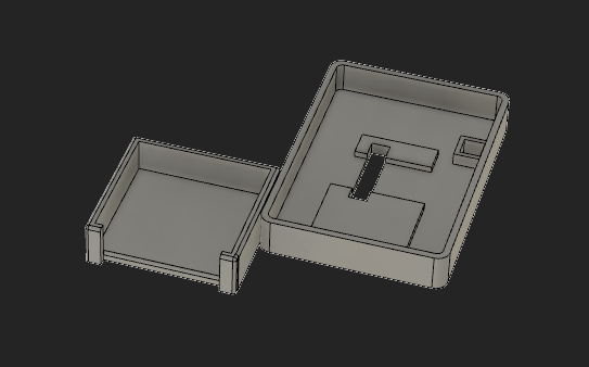
The 4 blocks house the neodymium magnets (∅ 6 mm) that hold the screw covers in place. The lower frame is for the touch sensor, the middle one for the display, and the top one for the wide-angle lens. Next to the slot for the touch button there's also an adhesive area for a 5dB antenna, since built-in antennas usually fall short on range. For the underside we need a frame for the DFPlayer as well as the ESP32 CAM module. After 3D printing, both are glued to the back of the large frame; the hole for the FLASH LED is clearly visible.
Now all that's missing is the mount for the speaker (there's not enough room for it up top) and the power supply. The empty housing already has a slot for this in the middle, so we simply take the original's dimensions and design a new 3D object.
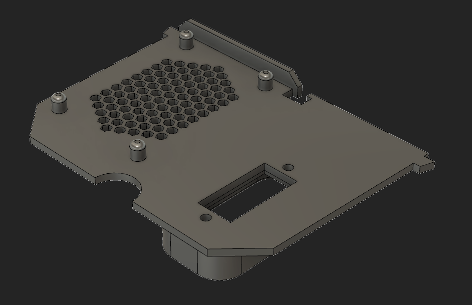
The speaker can be plugged directly onto the middle frame. The power supply also fits there. As with the water level sensor, I use converted USB power supplies. It can be firmly screwed to the middle frame.
Now we have a compact module that only needs to be connected to 230V and screwed to the empty housing with 4x M3 countersunk screws.
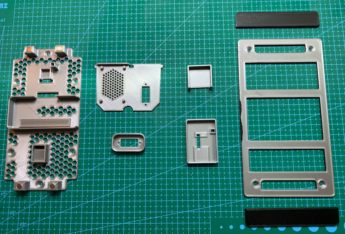
Everything for that needs to come out of the 3D printer:
The number of free pins on the ESP32 CAM module is just barely enough to connect everything. However, we do have to give up the SD slot for that, and share the FLASH light with the display's CS signal. We can still transmit and store images in Home Assistant (see the software section), and the FLASH light is sluggish enough not to notice the short CS pulses. Six signal lines go to the display and two to the DFPlayer.
| DoorBell Function | PIN @ESP32 CAM | PIN @ESP32 CAM | DoorBell Function | |
|---|---|---|---|---|
| FLASH light / CS - Display | GPIO4 | GND | GND | |
| RESET - Display | GPIO2 | GPIO1 | RxD - DFPlayer | |
| SPI CLK - Display | GPIO14 | GPIO3 | TxD - DFPlayer | |
| DC - Display | GPIO15 | 3.3V/5V | n/c | |
| SPI MOSI - Display | GPIO13 | GND | GND | |
| BUSY - Display | GPIO12 | GPIO0 | n/n (External Clock) | |
| GND | GND | GPIO16 | Touch Sensor | |
| 5V | 5V | 3.3V | 3.3V |
Once everything is plugged/soldered in, it's on to the programming…
No surprise here — ESPHome does the software work again. This time we don't even need any custom components, since all the needed functions are already implemented in ESPHome. We create a new device again and add the functional blocks:
The touch button becomes a simple binary sensor:
binary_sensor:
  - platform: gpio
    pin: GPIO16
    name: "Ring Door"
    id: ring_door_sensor
For the display we first need fonts and any special characters we want to use. Any TTF font can be used. The TTF files need to be copied to /config/esphome/fonts/.
# e-paper display 250x122 (128)
font:
  - file: 'fonts/ComicSansMS3.ttf'
    id: font_comic24
    size: 24
    ...
Then the SPI interface and the remaining pins need to be assigned. The lambda function at the end lets you freely program the display contents. The available rendering functions can be found in the Home Assistant documentation under Display Component.
spi:
  clk_pin: GPIO14
  mosi_pin: GPIO13

display:
  - platform: waveshare_epaper
    id: doorbell_display
    cs_pin: GPIO33
    dc_pin: GPIO15
    busy_pin: GPIO12
    reset_pin: GPIO2
    model: 2.13in-ttgo-dke
    full_update_every: 60
    update_interval: never
    reset_duration: 2ms
    rotation: 90
    auto_clear_enabled: true
    lambda: |-
    ...
Further up we also define a service for updating the display, so its contents can be redrawn on demand outside the normal schedule:
  services:
  - service: update_display
    then:
      - component.update: doorbell_display
For the camera, a maximum resolution of 800×600 proved to work well; higher resolutions didn't work for me. The CAM module's hard-wired pins need to be specified here:
# doorbell camera
esp32_camera:
  name: Doorbell_Cam
  vertical_flip: false
  horizontal_mirror: false
  external_clock:
    pin: GPIO0
    frequency: 20MHz
  i2c_pins:
    sda: GPIO26
    scl: GPIO27
  data_pins: [GPIO5, GPIO18, GPIO19, GPIO21, GPIO36, GPIO39, GPIO34, GPIO35]
  vsync_pin: GPIO25
  href_pin: GPIO23
  pixel_clock_pin: GPIO22
  power_down_pin: GPIO32
  #resolution: 640x480
  resolution: 800x600
  #resolution: 1024x768
  #resolution: 1280x1024
  #resolution: 1600x1200
  #jpeg_quality: 10
To get control over the FLASH light too, we need to add it like this:
output:
  #flashlight
  - platform: gpio
    pin: GPIO4
    id: gpio_4

light:
  #flashlight
  - platform: binary
    output: gpio_4
    id: cam_flash
    name: Doorbell Cam flash
The DFPlayer needs a serial interface for communication:
# DF MP3 Player
uart:
  tx_pin: GPIO1
  rx_pin: GPIO3
  baud_rate: 9600

dfplayer:
  on_finished_playback:
    then:
      logger.log: 'Playback finished event'
and a set of services:
  - service: dfplayer_play_folder
    variables:
      folder: int
      file: int
    then:
      - dfplayer.play_folder:
          folder: !lambda 'return folder;'
          file: !lambda 'return file;'
   ...
Beyond that, a few more sensors are built in to show WiFi signal strength, outdoor temperature and humidity, the time, and pre-selected texts on the display. Just a gimmick because we can…
The complete file is listed here once more:
After compiling and flashing, we integrate the doorbell.yaml module and all the key functions are now available in Home Assistant. Time to start on automation. Here's what our personal Node-RED implementation looks like:
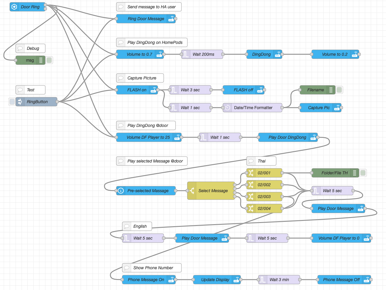
When the button on the doorbell panel is touched, the following now happens:
Of course you can also have it email you the captured image, turn on extra lighting, or feed the cat  …
…
Here's what the finished module looks like inside and outside (display pixelated):
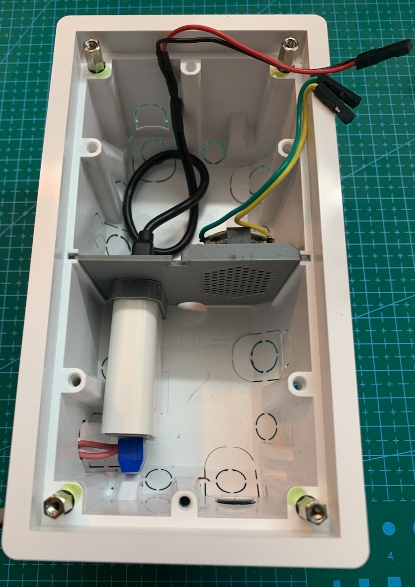
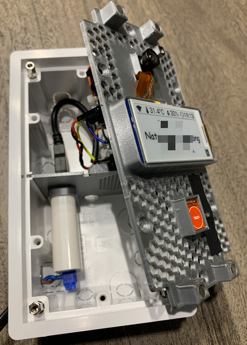
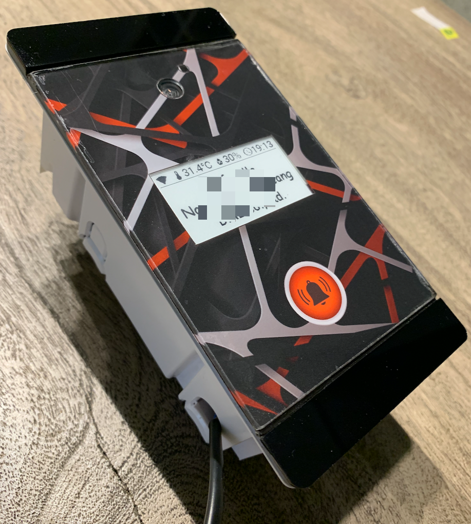
In dry testing in Germany, everything worked perfectly. Installation on-site in Thailand will happen in 2023. I'll keep reporting…
If you'd like to support my work, feel free to buy me a cappuccino or so: .


