- Deutsch (de)
- English (en)
The idea for the following circuit actually arose from the consideration that in addition to recording the consumption of the domestic heating system (here gas), it would also be very interesting to also record the outside and inside temperature. After all, the colder the weather, the more Ito heat. You may already have a temperature measurement system in use at home in the form of a weather station. So why not 'tap' into the wireless transmission of these sensors …
Incidentally, the above-mentioned energy collection (including electricity and water) is done using the free smart meter approach from http://www.volkszaehler.org. But more on that later.
The device should therefore receive and understand the IT+ sensor protocol and deliver the measured values recorded in this way to the smart meter via Ethernet on the intranet or internet. In order to be able to record independently of a network, a microSD interface for data storage would be a nice gimmick. Summarized again:
If you dare to use the IT+ protocol, you will find some sources (see links). The sensor always send every 4.5 seconds 5 bytes. The radio frequency is fixed at 868MHz. If the sensor can also measure the humidity, the value comes with it, if not then there is a fantasy value (= 106). Each sensor has an address coding. Caution there are sensors that use a new address after the battery has been changed. Several sensors can also be evaluated in parallel decoding the address. It should also be noted that no negative values are transmitted, as the temperature is always treated with an offset of 40 before transmission.
// ##### IT+ Frame #####
// Frame example (5 byte):
// 92h 03h 94h 59h 3Ch  --> Addr:32, Temp:-0.6, Hygro:89.0
// 92h 86h 24h 28h DEh  --> Addr:40, Temp:22.4, Hygro:40.0
// | || |  ||  ||  ||
// 9 28  624   28  DE
// | |    |    |   +--> CRC-8 (x8 + x5 + x4 +1)
// | |    |    +------> Hygro in %
// | |    |				  bit6..0 = hygro value (0..127, 106 = no hygro)
// | |    |				  bit7 = weak battery indicator (0=okay, 1=weak)
// | |    |				  example: 28 --> hygro 40%, battery okay
// | |    +-----------> Temp (T+40)*10 in °C
// | |					  nibble 1 = T10
// | |					  nibble 2 = T1
// | |					  nibble 3 = T0.1
// | |					  example1: 624 --> 62.4 - 40 = 22.4°C
// | |                    example2: 394 --> 39.4 - 40 = -0.6°C
// | +----------------> SensorID
// |					  bit7..2 SensorID (0..63)
// |					  bit1 = Restart flag (0=no restart, 1=restart-->new batt)
// |					  bit0 = unused (always 0)
// +------------------> Message length (number of nibbles that follow)
//                        example: 9 --> 9 nibbles follow
The following components are used in the hardware:
There is an inexpensive 868MHz RFM12 module for receiving (and, if you want, also for sending).
It is a Universal ISM Band FSK Transceiver and has already been extensively described elsewhere RFM12.
Communication takes place via a normal SPI interface in 16-bit transfer. The setting options are so versatile that you get desperate at the beginning until you finally are able to receive. Therefore, here is the init sequence that was successful for me:
// Bit	15	14	13	12	11	10	9	8	7	6	5	4	3	2	1	0
//  ←	1	0	0	0	0	0	0	0	el	ef	b1	b0	x3	x2	x1	x0	0x8008
//		1	0	0	0	0	0	0	0	1	1	1	0	0	1	1	1	0x80E7
rf12_trans(0x80E7);			// ena TX latch, ena RX FIFO, 868MHz, 12.0pF

//		1	0	0	0	0	0	1	0	er	ebb	et	es	ex	eb	ew	dc	0x8208
//		1	0	0	0	0	0	1	0	-------- do on the fly ---------

// ←	1	1	0	0	1	1	0	0	0	ob1	ob0	lpx	dly	dit	bw1	bw0	0xCC77
//		1	1	0	0	1	1	0	0	0	1	1	1	0	1	1	1	0xCC77
rf12_trans(0xCC77);			// drv 5/10MHz, low-power OSC, no dith., band width 256kB

// ←	1	1	0	0	0	0	0	0	d2	d1	d0	v4	v3	v2	v1	v0	0xC000
//		1	1	0	0	0	0	0	0	0	1	0	0	1	0	0	1	0xC049
rf12_trans(0xC049);			// 1.66MHz, 3.1V

// ←	1	0	1	0	f11	f10	f9	f8	f7	f6	f5	f4	f3	f2	f1	f0	0xA680
//		1	0	1	0	0	1	1	0	0	1	1	1	1	1	0	0	0xA67C
rf12_trans(0xA67C);			// FREQUENCY 868.300MHz

//	 ←	1	1	0	0	0	1	1	0	cs	r6	r5	r4	r3	r2	r1	r0	0xC623
//		1	1	0	0	0	1	1	0	0	0	0	1	0	0	1	1	0xC613
rf12_trans(0xC613);			// DATA RATE 17.241 kbps

//	 ←	1	0	0	1	0	pi	d1	d0	i2	i1	i0	g1	g0	r2	r1	r0	0x9080
//		1 	0	0	1	0	1	0	0	1	0	1	0	0	0	0	0	0x94A0
rf12_trans(0x94A0);			// VDI, fast, 134khz, LNA 0dB, DRRSI -103 dB

//	 ←	1	1	0	0	1	1	1	0	b7	b6	b5	b4	b3	b2	b1	b0	0xCED4
//		1 	1	0	0	1	1	1	0	1	1	0	1	0	1	0	0	0xCED4
rf12_trans(0xCED4);			// SYNC=2DD4

// ←	1	1	0	0	0	0	1	0	al	ml	1	s	1	q2	q1	q0	0xC22C
//		1	1	0	0	0	0	1	0	1	0	1	0	1	1	0	0	0xC2AC
rf12_trans(0xC2AC);			// autolock, dig. filter, mid level

// ←	1	1	0	0	1	0	1	0	f3	f2	f1	f0	sp	al	ff	dr	0xCA80
//		1	1	0	0	1	0	1	0	1	0	0	0	0	0	1	1	0xCA83
rf12_trans(0xCA83);			// FIFO level =  8, 2-SYNC, sync fill, FIFO ena, reset off

// ←	1	1	0	0	0	1	0	0	a1	a0	rl1	rl0	st	fi	oe	en	0xC4F7
//		1	1	0	0	0	1	0	0 	1	0	0	0	0	0	1	1	0xC483
rf12_trans(0xC483);			// AFC if VDI=0, unlimited range, AFC OE+EN

// ←	1	0	0	1	1	0	0	mp	m3	m2	m1	m0	0	p2	p1	p0	0x9800
//		1	0	0	1	1	0	0	0	0	1	0	1	0	0	0	0	0x9850
rf12_trans(0x9850);			//  no inv, deviation 90kHz, MAX OUT

// ←	1	1	1	r4	r3	r2	r1	r0	m7	m6	m5	m4	m3	m2	m1	m0	0xE196
//		1	1	1	0	0	0	0	0	0	0	0	0	0	0	0	0	0xE000
rf12_trans(0xE000);			// NOT USE

// ←	1	1	0	0	1	0	0	0	d6	d5	d4	d3	d2	d1	d0	en	0xC80E
//		1	1	0	0	1	0	0	0	0	0	0	0	0	0	0	0	0xC800
rf12_trans(0xC800);			// NOT USE
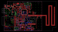
 The PCB was matched to the SP 2000 SW housing from STRAPUBOX. So that everything simply fits into SMD components are used where it makes sense.
When it comes to sockets (Power / Ethernet), I'm still a fan of thru-hole - because of the stability. The soldering took place again in the pizza pan as described in the c't Hacks.

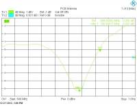
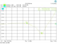
 An antenna must also be connected to the RFM12 module. Usually 1/4 lamba so about 8.3cm. But since there was still space on the PCB, I dared to try a PCB variant in a meandering structure. There is also a nice design note from Texas Instruments (DN024). The result was a bit off, however, because the
 of my favorite PCB maker turned out a bit different in reality. The maximum gain was about 790MHz and could then be reduced to 868MHz with a final -6dB gain. This means that reception through concrete ceilings or walls is also feasible.
The software was created with AVR STudio 6 and an AVR-Dragon as a debugger. An UART I/F is on board as support, which then outputs the printf instructions on my MAC via a level converter and the RS232/USB adapter without complaint. A command I/F also allows direct control via the same interface. A small web server is also integrated for normal operation. The entire package including Ethernet and SD support requires approx. 85K FLASH and 12.5K RAM memory.
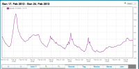
 If you want to try the recording live on my web server: http://vz.rbulla.de. The UUID for the outside temperature (in Langenfeld-Rheinland) is:
 e62976c0-7109-11e1-a585-8762f86249c1 .