Sidebar
This is an old revision of the document!
Table of Contents
TRÅDFRI Module
In an earlier article we could already see how a TRÅDFRI module can be removed from an IKEA lamp and used for your own LED projects. The module itself is used in various IKEA devices, including the lamps and drivers, as well as:
- TRÅDFRI socket
- TRÅDFRI gateway
- TRÅDFRI repeater
- TRÅDFRI motion detector
- FYRTUR blind
The function of the pins is then accordingly. Here is an overview:
| TRÅDFRI Pin | Lamp white | Lamp white spectrum | Power Plug | FYRTUR |
|---|---|---|---|---|
| PA0 | open | open | Button | Up Button |
| PA1 | open | VCC | NTC | LED |
| PA12 | - | PWM2 | Relay | TxD |
| PA13 | PWM | PWM1 | LED | RxD |
| PC10 | - | - | - | Down Button |
The module is controlled by an EFR32MG1PXXXF256 controller from Silicon Labs. He has a debug interface that is also available on the module. This is ARM's Serial Wire Debug (SWD) interface with 2 wires.
Debugger
A debugger is required to be able to read or write to the FLASH. An inexpensive variant is again available from Ebay. You can find more information, among other things here.
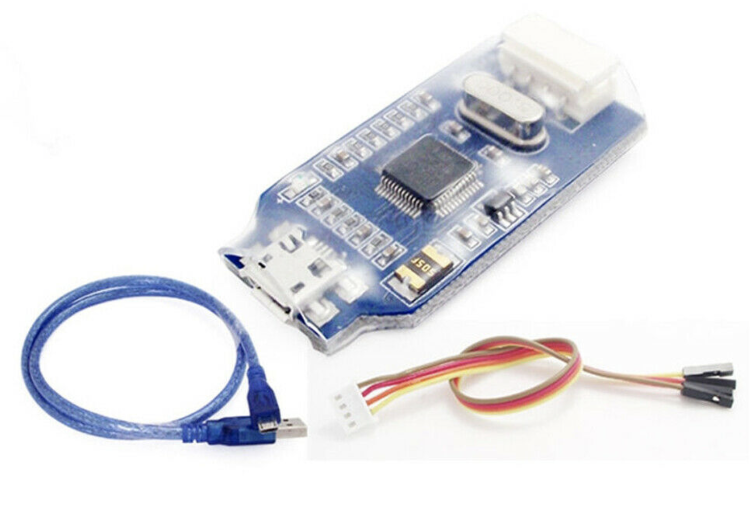
The 4 wires of the debugger are to connect to the module as follows:
| JLINK | TRÅDFRI Modul |
|---|---|
| VCC | VCC |
| SWDIO | PF1 |
| SWCLK | PF0 |
| GND | GND |
In addition, the module must be supplied with 3.3V. J-Link from SEGGER is available as software. Version V648b ran stable on my Mac.
Read out
In the terminal window we then enter the following command (adapt path):
<pfad>/JLinkExe -If SWD -Speed 5000 -Device EFR32MG1PXXXF256
The J-Link> prompt appears. To connect to the Cortex-M4 simply enter connect and if successful, the response looks like this:
J-Link>connect
Device "EFR32MG1PXXXF256" selected.

Found SWD-DP with ID 0x2BA01477
Found Cortex-M4 r0p1, Little endian.
FPUnit: 6 code (BP) slots and 2 literal slots
CoreSight components:
ROMTbl 0 @ E00FF000
ROMTbl 0 [0]: FFF0F000, CID: B105E00D, PID: 000BB00C SCS
ROMTbl 0 [1]: FFF02000, CID: B105E00D, PID: 003BB002 DWT
ROMTbl 0 [2]: FFF03000, CID: B105E00D, PID: 002BB003 FPB
ROMTbl 0 [3]: FFF01000, CID: B105E00D, PID: 003BB001 ITM
ROMTbl 0 [4]: FFF41000, CID: B105900D, PID: 003BB923 TPIU-Lite
Cortex-M4 identified.
The Cortex-M4 of the TRÅDFRI module has four FLASH areas that we have to consider:
| Area | ADDR | Size |
|---|---|---|
| MAIN | 0x0 | 0x40000 |
| USER | 0xfe00000 | 0x800 |
| LOCK | 0xfe04000 | 0x800 |
| CHIP | 0xfe08000 | 0x400 |
To read out and save, we enter the following commands:
J-Link>savebin TRADFRI_main.bin 0x0 0x40000
Opening binary file for writing... [/Users/rolf/Projekte/TradFri/TRADFRI_main.bin]
Reading 262144 bytes from addr 0x00000000 into file...O.K.

J-Link>savebin TRADFRI_chip.bin 0xfe08000 0x400
J-Link>savebin TRADFRI_lock.bin 0xfe04000 0x800
J-Link>savebin TRADFRI_user.bin 0xfe00000 0x800
With the command J-Link> verifybin TRADFRI_main.bin 0x0 the read out can be verified again.
Fortunately, all of the modules I read were not read-protected so far.
If we collect all four files, we can now reprogram any module and thus obtain the desired function. In my case I took the TRÅDFRI modules out of the repeater and converted them into blind modules and used them here.
Programming
Programming is just as easy as reading out with the following commands:
J-Link>loadbin TRADFRI_blind_main_2_2_009.bin 0x0
Downloading file [TRADFRI_blind_main_2_2_009]...Comparing flash   [100%] Done.
Erasing flash     [100%] Done.
Programming flash [100%] Done.
Verifying flash   [100%] Done.
J-Link: Flash download: Flash programming performed for 1 range (188416 bytes)
J-Link: Flash download: Total time needed: 6.193s (Prepare: 0.112s, Compare: 0.298s, Erase: 2.700s, Program: 2.931s, Verify: 0.143s, Restore: 0.007s)
O.K.

J-Link>loadbin TRADFRI_blind_chip.bin 0xfe08000
J-Link>loadbin TRADFRI_blind_lock.bin 0xfe04000
J-Link>loadbin TRADFRI_blind_user.bin 0xfe00000
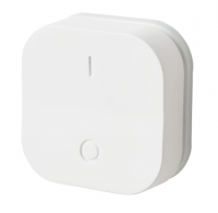
TRÅDFRI on/off switch
The same procedure can also be used for other TRÅDFRI devices that do not use this module. The circuit structure is always the same. All you have to do is find the four connections on the circuit board. These are always available as pads for the module test and are therefore easily accessible.
For the blind project I converted the standard TRÅDFRI on/off switch into a button for the blind. Unfortunately, you can't buy one individually.

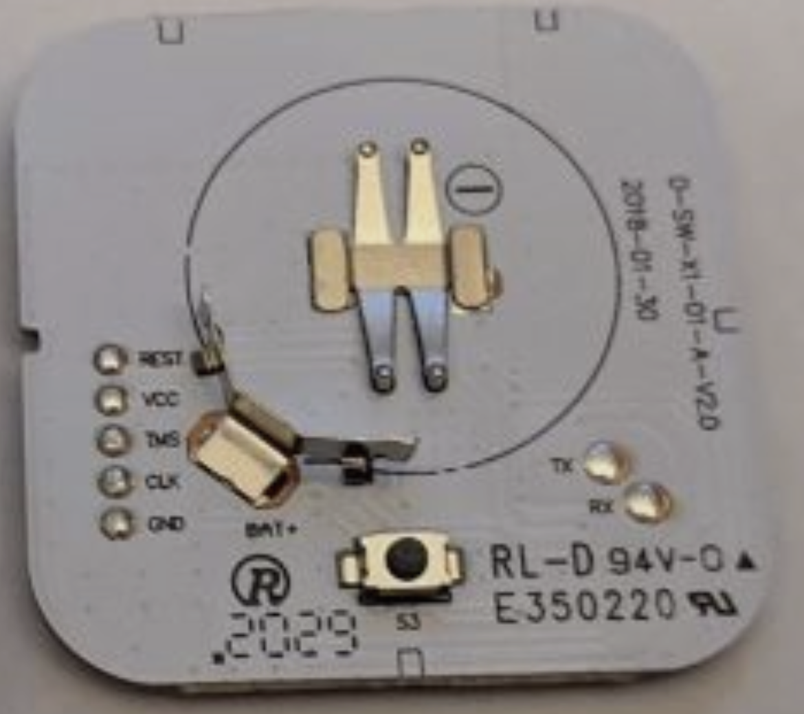
How to open the button is here well described. The connections for programming are labeled on the back of the PCB and the connection to the debugger is shown as follows:
| JLINK | TRÅDFRI Taster |
|---|---|
| VCC | VCC |
| SWDIO | TMS |
| SWCLK | CLK |
| GND | GND |
Update
Alle TRÅDFRI Komponenten unterstützen Over-The-Air (OTA) Updates. Darum braucht man sich nicht zu kümmern da es im Hintergrund zum Beispiel durch das Gateway erfolgt. Wollen wir beim Umprogrammieren jedoch gleich die aktuelle Firmware flashen, dann können wir die Daten auch direkt vom IKEA OTA Server holen. Findige Entwickler haben dazu ein Python Script geschrieben. Mit Hilfe dieses Script werden alle auf dem Server vorhanden Files heruntergeladen. Das Beispiel für das Rollo sieht dann so aus 10037585-5.1-TRADFRI-connected-blind-2.2.009.ota.ota.signed
Es wird allerdings nur der MAIN Bereich des FLASH aktualisiert. Die Bereiche USER, LOCK und CHIP ändern sich nicht und sind somit auch nicht online. Will man also ein Modul in eine andere Funktionalität umprogrammieren, so muss man es zumindest einmal selber ausgelesen haben um an die Daten für USER, LOCK und CHIP zu kommen.
Die geladenen Daten sind in einem exotischen Format gekapselt mit der Abkürzung NGIS. Hier war auch wieder etwas Arbeit nötig um das Format zu entschlüsseln und die Binärdatei zu extrahieren. Eine tolle Unterstützung war dabei übrigens das Program Synalyze it! Pro. Das Graph File liegt im Downloadbereich bereit.

Zum Extrahieren habe ich ebenfalls ein Python Script geschrieben das auch im Downloadbereich liegt. Bei den bisherigen Tests war die extrahierte Version binäridentisch zur ausgelesenen.
Downloads
Donate
If you line my articles feel to donate a cappuccino or so…
