
Translations of this page?:
- Deutsch (de)
- English (en)
Our property is - as is common here in Thailand - enclosed by a two-meter-high wall. It keeps out animals like stray dogs but also snakes and the like. From the inside, you can of course plant this wall lushly.
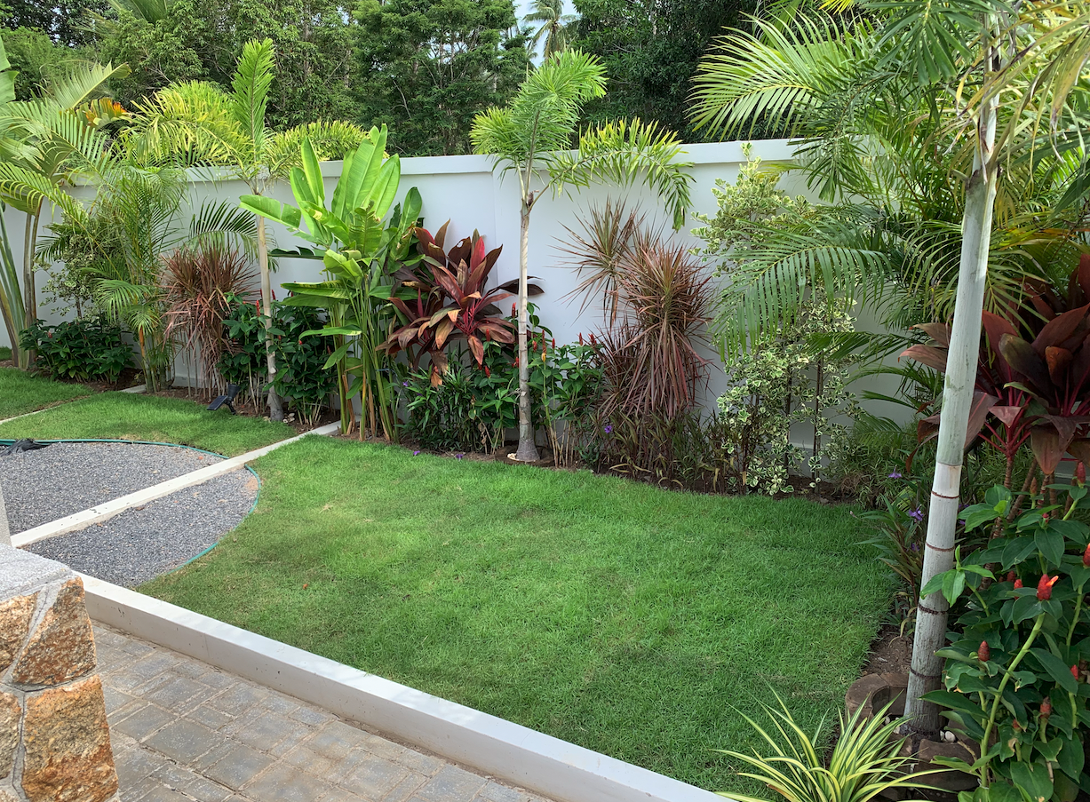
A nice visual treat would be indirect lighting with dimmable LED spotlights behind the plants. We're talking about a length of roughly 40m that needs to be lit. A solution was needed…
We have a 230V supply running through the garden, but it's neither switchable nor dimmable, since other loads such as outdoor outlets and the ground lighting are connected to it. I ruled out adding separate wiring from the house after failing to trace the path of the underground conduits. So something wireless was needed instead, which (as always) also needs to be integrable into Home Assistant.
Beforehand I'd already picked the LED spots based on looks, output, price, and size. I settled on a 5W/600lm floodlight with 12V AC/DC supply in an IP65 housing from the Thai Amazon: LAZADA.
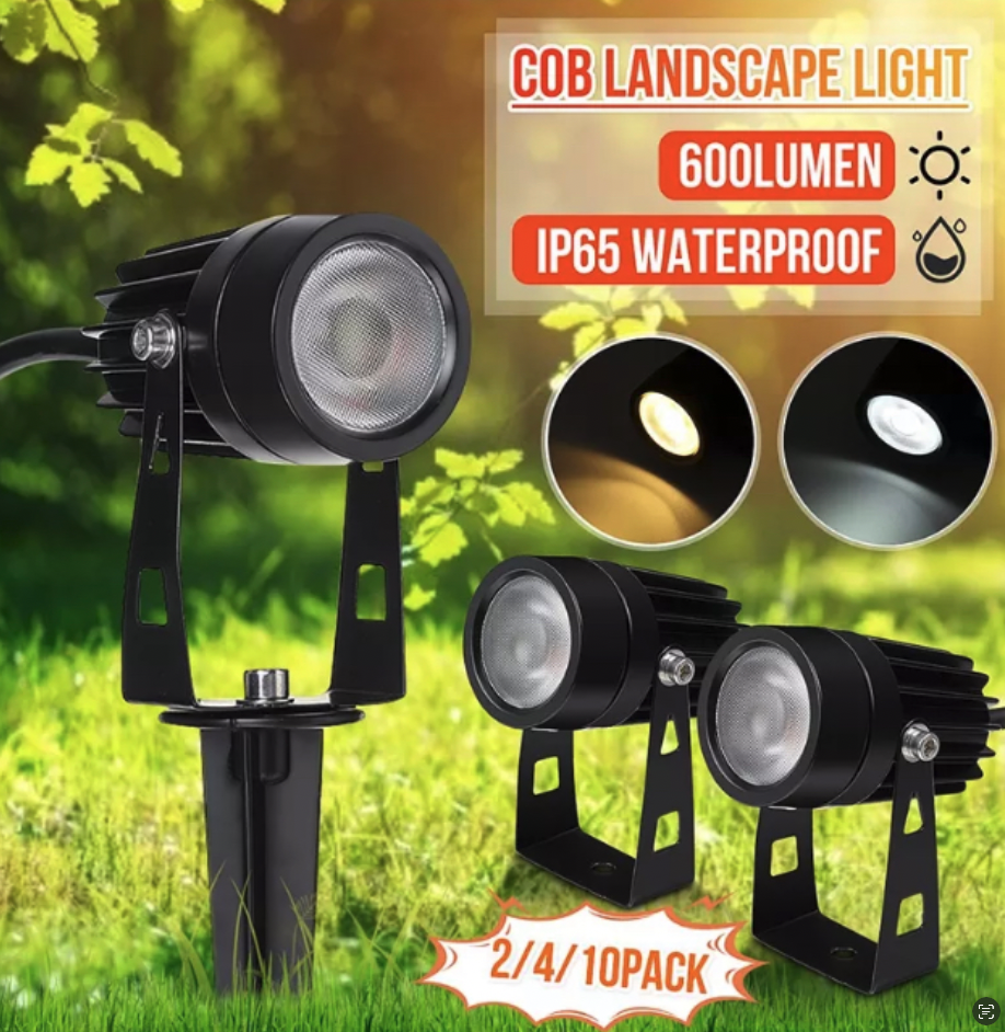
At a price of under €4 each, it really does come in a waterproof aluminum housing with an internal control board, and it works! The light source is a 3mm LED driven at 21.5V with a constant current of 266mA. The higher voltage is produced by a boost regulator (BP1808), which also has an unused DIM input. This can be driven either with an analog signal or a PWM signal. An initial test with a 500Hz PWM showed the desired dimming behavior.
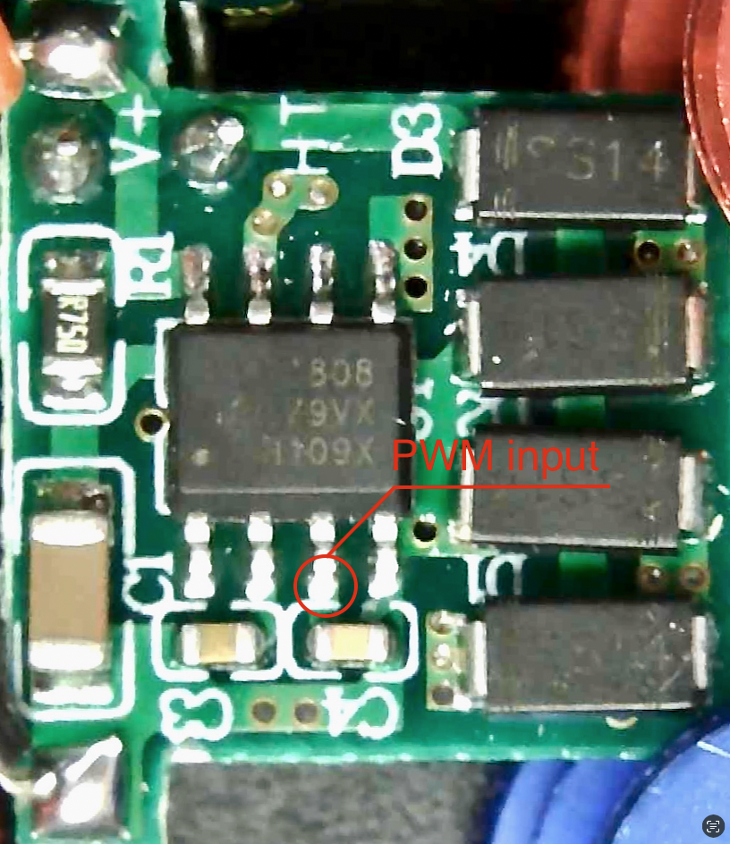
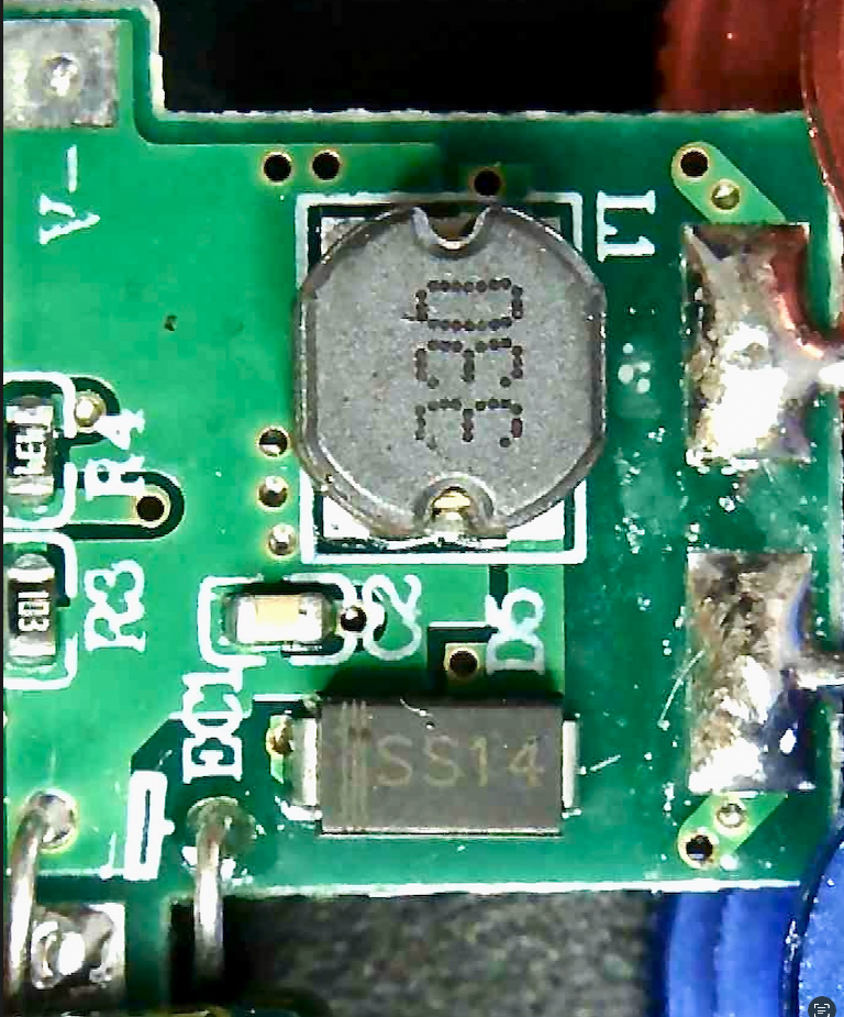
Now we just need an idea for how to provide the dimming level selected in Home Assistant as a PWM signal for each spotlight. The LED's housing doesn't allow for a bulky solution. DMX512 seems a bit overkill here. So why not try a proprietary approach for once.
Early attempts at communicating over the low-voltage lines failed for reliability and scalability reasons. There is actually a clever approach for that: Simple Circuit Communicates Over Low-Voltage Power Lines. Implemented with an ATTINY85, it basically worked between two transceivers over 10m at 2400 baud, but it's not suitable out-of-the-box for this application.
For data transmission over several tens of meters, RS485 always comes to mind too. Suitable driver ICs are widely available and a standard UART is enough as the communication interface. To cut to the chase, this idea did in fact lead to success. Here's the write-up…
The LED boost driver with the BP1808 needs to be extended with a circuit for receiving serial data over RS485, and it needs to be as small as possible. The interior of the lamp housing only holds about 40mm x 20mm. For the control CPU I went with an ATTINY85 from Microchip, available in a small 8-pin SOIC package. It also has an EEPROM (e.g. for the lamp ID), an on-chip oscillator, and a debugWIRE interface, which allows in-place debugging and simplifies software development. The RS485 driver is available e.g. from MAXIM, also in an SOIC8 package.
Put together, the schematic looks like this:
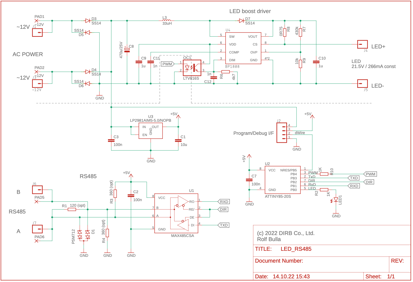
The LED boost driver is identical to the original version and just extended with PWM control. Since my early attempts caused a couple of hardware failures (ATTINY85 + BP1808) due to overvoltage, the PWM signal is galvanically isolated with an optocoupler (OC1). Optional termination resistors are also provided on the RS485 interface (R1, R3, R4). The MAXIM chip operates in half-duplex, so we also control the direction (receive or transmit) via the ATTINY85. The last free output on the CPU drives a status LED (LED1), which helps with debugging and commissioning, especially when you leave the POWER LED disconnected.
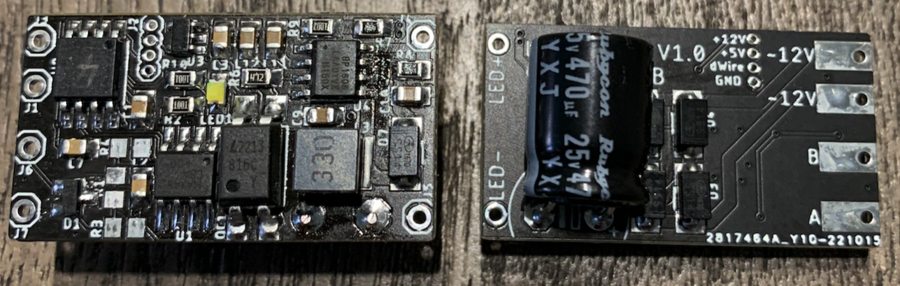
Given the geometric constraints, there's no avoiding double-sided assembly. But the second side only holds the four SS14 diodes (D3-D6) of the bridge rectifier and the large through-hole capacitor C8. These components have to be hand-soldered, but the rest can be 'baked' in the reflow oven beforehand (I use a T-962).
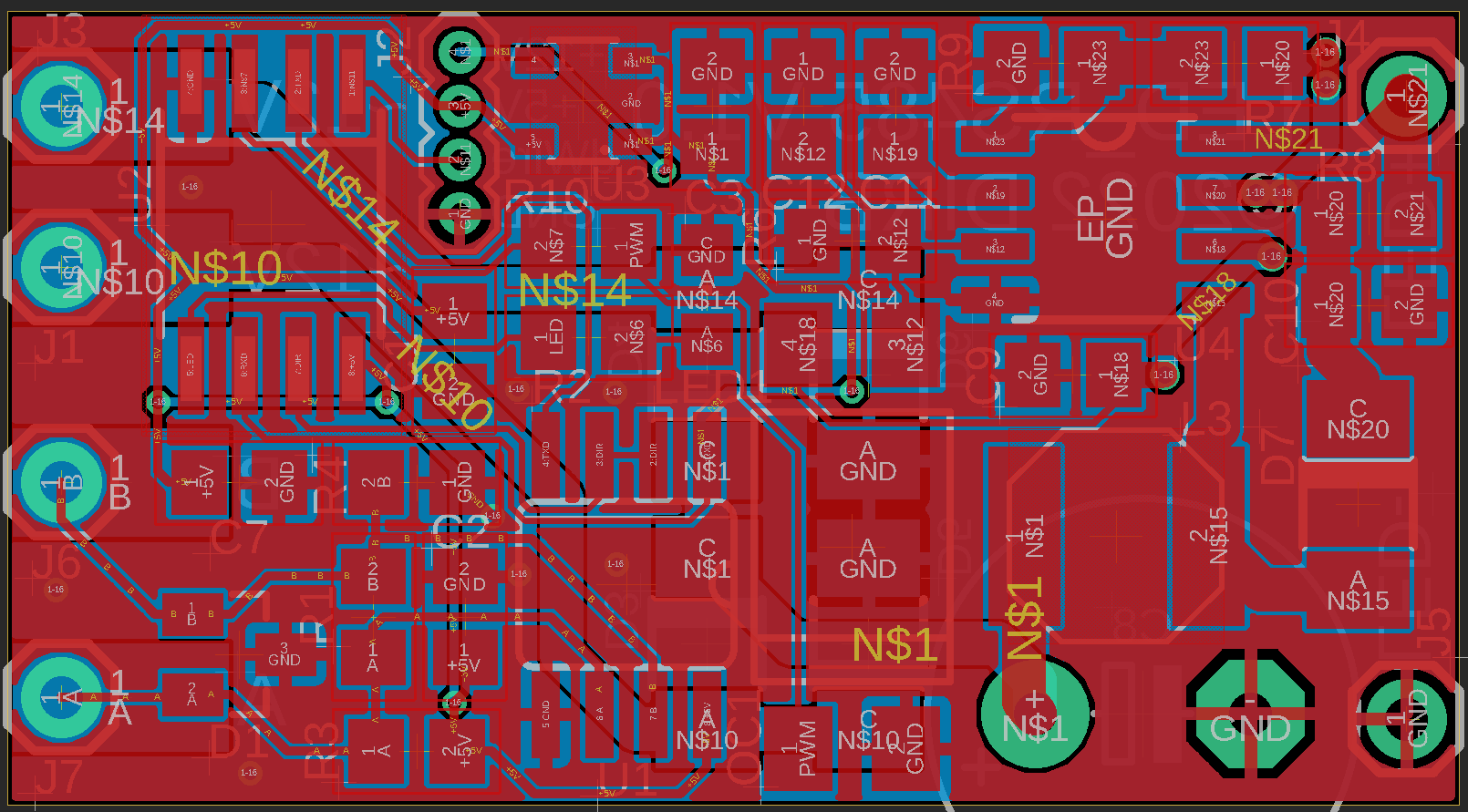
At 39.3mm x 19mm, the board size is already pushing the mechanical limit, but it fits. In reality the front side of the board does look pretty densely packed. The hand-written 4 on the CPU is the programmed ID of the LED. This number lets you address the spotlight individually. More on that later.
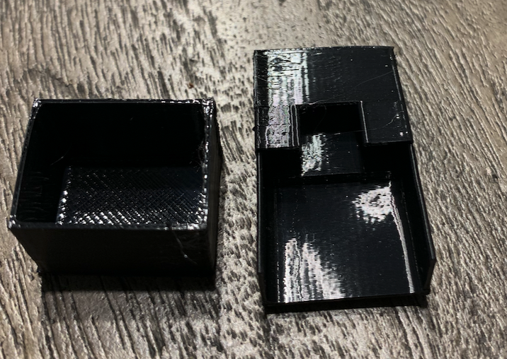
To install the board electrically isolated inside the housing, I 3D-print a two-part cover from flexible TPU. Slid over both ends of the board, it keeps everything protected against unwanted short circuits. The STL file is available in the downloads section.
We've settled on RS485 for the physical layer, but we still need a data link layer that increases transmission reliability - after all, the spotlights shouldn't flicker just because there's an unwanted signal party going on on the bus. I found a lean solution online that also includes a Python version for the PC. It's called MIN (Microcontroller Interconnect Network). The payload can be freely defined, and its contents are protected by a 32-bit CRC.
In my implementation a frame consists of 13 bytes:
which is answered by the addressed spotlight depending on the function. Broadcast commands don't get a response from the other side. Here's a quick command overview:
// min_id (8-bit):
// 0x00-0x0f 	ID LED lamp 1 - 16 -> function + value
// 0x10-0x1F	Response ID LED lamp 1 - 16
// 0x3E         all LED -> function + value (no response)
// 0X3F         -
//
// Payload / Response:
// Byte 1	Function
//  0x00	LED Off
//  0x01	LED Off (stored delay)
//  0x02	LED On
//  0x03	LED On (stored value/delay)
//  0x04	Set stored value/delay
//  0x05	Get stored value/delay
//  0x06	Status
//  0x07	Status LED on/off
// Byte 2	Value	0..255 	LED brightness
// Byte 3	Delay	0..255 	LED fade up/down delay

// Payload Response Error:
// Byte 1	0xFF
// Byte 2	Error code
//  0x00	Payload size wrong (byte 3 = wrong size value))
//  0x01	Unknown Function
// Byte 3	<not used>
Individual brightness and fade values can also be stored in the spotlights, which then allows different brightness levels in response to broadcast commands. The protocol is implemented in the min.c module. We also need a software UART emulation, since the ATTINY85 doesn't have a hardware variant. The baud rate is fixed at 9600 baud so nobody has to sweat, giving a frame length of about 14ms. Using the free MPLAB IDE and the free tier of Microchip's XC8 C compiler, the software can be compiled and flashed onto the chip.
Out of the factory, the ATTINY85's debugWIRE interface is disabled and programming is only possible via ISP. That ties up several pins of the processor and can't be done on-board. So it's worth getting a small programming adapter (socket) for the SOIC8 (200mil) package and programming the fuses with it before assembly. After that the software can also be programmed via the 1-pin dWire interface.
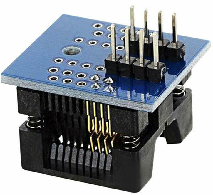
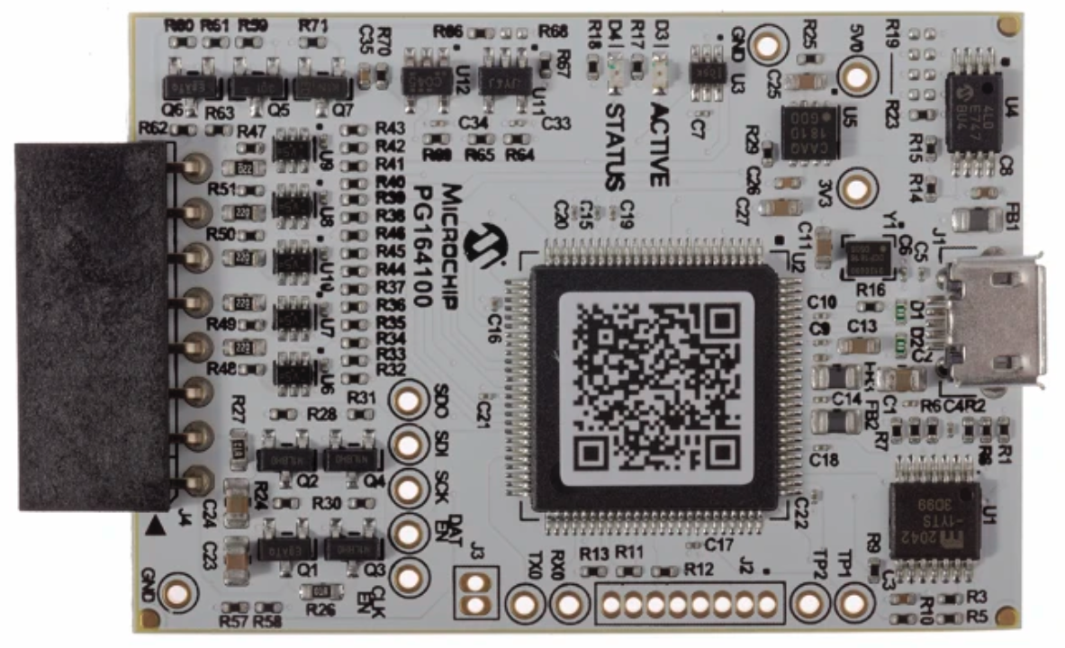
The debug and programming tool of choice remains the SNAP (PG164100). All of these tools are easy to find and affordable for a DIY budget on online marketplaces or auction sites.
Once the spotlights are programmed as described above, the LEDs can already be addressed from a PC via a USB-RS485 converter. A Python variant is also available for the MIN protocol.
My goal, though, is to integrate the spotlights into Home Assistant (HA). For that we need a gateway that exposes the spotlights as Lights in HA and also includes a UART server so we can send arbitrary commands to the LEDs too. Sounds complicated, but it isn't with ESPHome.
For the UART server there's already a nice solution here. We just need to slightly adapt the code, switching the direction of the RS485 driver before and after sending. The lines marked with ### were added into the send routine. The full modified code is available in the downloads section.
void StreamServerComponent::write() {
    digitalWrite(DIR_PORT, HIGH);   // ### set direction to receive
#if ESPHOME_VERSION_CODE >= VERSION_CODE(2021, 10, 0)
    this->stream_->write_array(this->recv_buf_);
    this->recv_buf_.clear();
#else
    size_t len;
    while ((len = this->recv_buf_.size()) > 0) {
        this->stream_->write(this->recv_buf_.data(), len);
        this->recv_buf_.erase(this->recv_buf_.begin(), this->recv_buf_.begin() + len);
    }
#endif
    this->stream_->flush();         // ### Added by DIRB
    digitalWrite(DIR_PORT, LOW);    // ### set direction to receive
}
To expose the LEDs as lights we again write a custom component. The following C program garden-leds.h provides a float output for Home Assistant and includes a lean implementation of the MIN protocol.
Now we create a new device in ESPHome again and point it at the two custom codes stream-server and garden-leds.h.
We already copied the first part into config/esphome/my_components/stream-server earlier, and the second file into config/esphome.
esphome:
  name: garden-leds
  includes:
    - garden-leds.h

external_components:
  - source:
      type: local
      path: my_components
    components: [stream_server]
And finally, the setup of the light and the server:
uart:
  id: uart_min
  tx_pin: GPIO1
  rx_pin: GPIO3
  baud_rate: 9600

stream_server:
  uart_id: uart_min
  port: 6638

output:
  - platform: custom
    type: float
    lambda: |-
      auto min_led_pwm = new Min_Led();
      App.register_component(min_led_pwm);
      return{min_led_pwm};
    outputs:
      id: led_pwm

light:
  - platform: monochromatic
    name: "Garden Wall"
    output: led_pwm
If needed, the pins tx_pin, rx_pin for the serial interface and the direction pin DIR_PORT in garden-leds.h will need to be adapted for your own hardware.
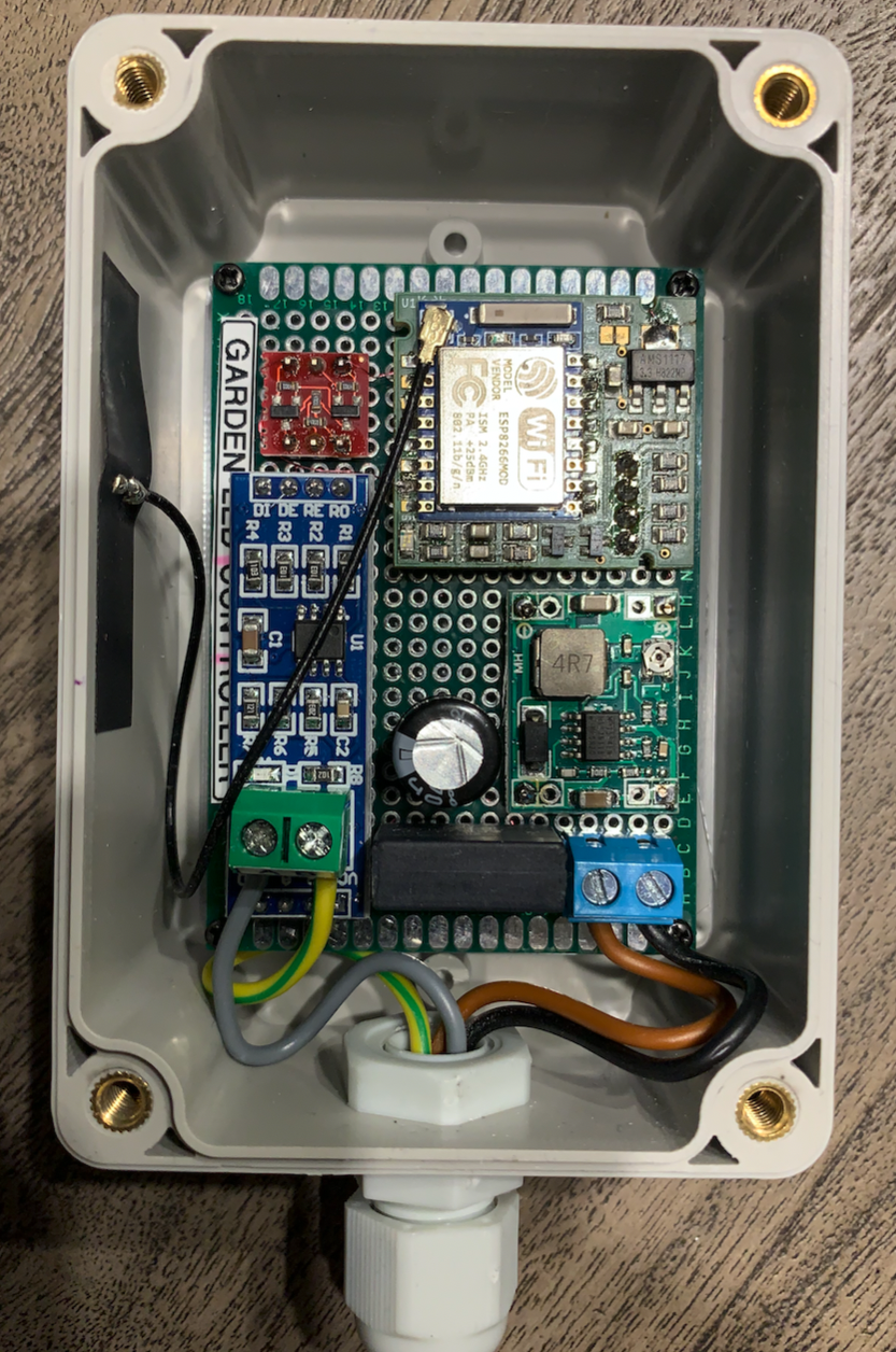
For the hardware, besides the ESP module of choice, we need an AC/DC step-down regulator from ~12VAC to +5VDC, a 5V↔3V level shifter, and an RS485 driver module. That's also readily available on auction sites. The wiring is simple - here's my version:
| ESP8266 | RS485 Driver |
|---|---|
| GPIO1 | DI |
| GPIO3 | RO |
| GPIO13 | RE+DE |
| +5V | VCC |
| GND | GND |
Soldered onto a piece of prototype board and packed into a waterproof housing, the whole thing looks like this:
Between the spotlights and the gateway we need a 4-core cable. Since I route it outside inside a waterproof conduit, a PVC hose cable H03VV-F4G0.75 is enough for me. When wiring, simply connect the 12VAC and the two signals A + B in a chain from one fixture to the next:
| Gateway | Spot 1 | Spot 2 | … | Spot n |
|---|---|---|---|---|
| ~12V | ~12V | ~12V | … | ~12V |
| ~12V | ~12V | ~12V | … | ~12V |
| A | A | A | … | A |
| B | B | B | … | B |
Depending on the number of spots, you'll also need a sufficiently powerful transformer for ~230V to ~12V. Here you can, for example, reuse a used halogen transformer - these can be found plentifully in second-hand markets. I got my 200W ABB transformer, fuses included, there for €8.
Once we connect up the fully wired assembly, the light with dimming function is available in Home Assistant. The fade time can also be set there and defaults to 1s. Thanks to the stream server we can also access the LEDs from, say, a PC. For that I wrote a small Python program (source code in the downloads section).
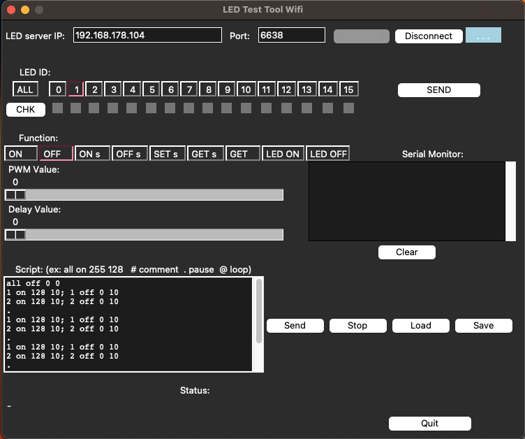
This lets you run any function on all or individual LEDs. CHK searches for connected LEDs, and at the bottom there's a simple script editor that allows programming sequences, with a step time of 100ms, i.e. 10Hz. A nice gimmick for New Year's Eve or other parties.
At the moment there's only a test setup with two spotlights, and it works very well. The full outdoor installation won't happen until 2023. I'll report back…
If you'd like to support my work, feel free to buy me a cappuccino or so: .


