TechWiki
GW60 Rollo
- GW60 Superrollo
- Hardware
- Programming
- S/W extension
- TRADFRI Modul
- Modul H/W
- Programming
- Tools
- GW60 TRADFRI adapter
- Schematic
- Programming adapter
- Housing
- Integration
The original article you will find here
I bought my Chinese Laser Cutter from a German vendor in 2014 in order get a Laser Class 1 system. A Class 1 laser is safe under all conditions of normal use. No need for any eye protection which increases the WAF (wife acceptance factor). After some trials I faced the common issue with MoshiDraw and the corresponding controller (MS10105 V4.5). One of the severe drawbacks of V4.5 is the missing link between controller board and laser power control. The laser power has to be set manually for each job. The next versions of the controller (V4.6) solves this bottleneck but it's still a closed system. And the Chinese MoshiDraw software is ugly… My new objective was clear: I have to move to open source (LAOS). The following pages will describe the findings I had due to some differences in the actual machine version.
My laser cutter hosted a MY JG40W power supply with PWM power control input.

I used the following connectors:
| K- | trigger button - | to panel button |
| K+ | trigger button + | to panel button |
| G | Ground | to LAOS main controller (GND) and level shifter unit |
| IN | PWM input, 0/5V, 0…100% duty cycle | to LAOS main controller (Laser PWM) via level shifter unit |
| 5V | +5V output | for level shifter unit only |
| 24 | +24V output | n/c |
| G | Ground | to LAOS main controller (GND) |
| 5V | +5V output | n/c |
| L | Laser on | to LAOS main controller (Laser On) |
24V and 5V from this power supply are not used in my installation. There are separate PSUs available in order to keep the controller operating while the laser is powered off (laser class 1 safety issue).
Laser power controller Here the actual system is much more modern and supports a digital power adjustment in 1/10, 1 and 10% steps (but still suffers from missing link to main control board). The board is called 6C6879-LEDPAD-A. It was replaced by an I2C-Panel of LAOS.
The new control panel I added a LED showing the laser activity and a button to trigger the laser. The rest is supported by I2C-Panel. The front design file (SVG) is attached.
Signal integrity issue LAOS main board uses optocouplers for laser control (if you don't use the transistor output). In a lot of config files I found that PWM frequency is set to 1KHz. In my system the frequency from power control panel was 21KHz. But this is a little fast for the optocouplers. The ground level get weak even with a pull-up of >470Ohm. The picture shows the signal at optocoupler (reference in yellow is the transistor output w/o optocoupler).
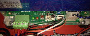
Therefore I decided to build a level shifter unit. With an op-amp (TLC271) the level at the optocoupler is judged at approx. 3V (with few 0.1V hysteresis). A following schmitt-trigger (74LS14) drives the laser PSU directly. Power (+5V) for this circuitry is provided by the laser PSU in order not to jeopardize the isolation.
The level shifter soldered on a small PCB:
New exhaust hose adapter My laser cutter was equipped with fan capable to handle up to about 150m3/h air volume. That wasn't enough in a closed room. Therefore I upgraded to 400m3/h fan and changed the exhaust hose adapter. In order to be most flexible the adapter hosts a standard 100mm duct join. It's based on 3mm birch plywood. For sealing on machine side I used a 5mm thick foam tape from 3M. The part can be found on http://www.thingiverse.com/thing:454820
My Laser cutter after all modifications (until m/o Aug 2014)