Table of Contents
DAB+ Module
Motivation
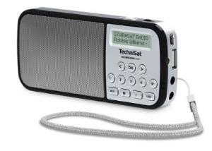
In the age of 'music streaming', terrestrial radio listening seems antiquated. In the absence of WLAN or mobile communications, however, it can be an alternative to stay connected to the world, at least while consuming. FM (UKW) transmission was first trial took place in Germany almost 100 years ago (1925). And actually FM was supposed to be discontinued in 2012, but this only became reality in the cable network. To the delight of motorists with conventional analogue radios. The current digital successor DAB+ (the previous, incompatible and not very successful DAB was discontinued) is at least visible on the market and there are a number of inexpensive DAB+ receivers under €30. I decided to try out a TechniSat TECHNIRADIO RDR:
The radio has all the important functions for digital reception in a handy housing. But what if you had a small, programmable FM/DAB+ module that you could use in your own projects? A new project is born…
First attempts
By the way, I had my first DIY attempt with DAB+ in 2014 with a module (T2-L4A-8650C) from the Taiwanese company KeyStone Semiconductor. Here is the related thread in microcontroller.net (German).
In the hobby area, however, the selection is still very limited. In the pandemic year 2020 I could only find two modules:
- DAB/DAB+/FM Radio Shield for Arduino for ca. £60,-
- uGreen DAB Board for ca. 45,-€
What all of these receivers have in common is that they are based on an IC SI4684-A10 from the US company Skyworks Solutions Inc. (formerly Silicon Labs.) which is available for approx. 15,- € from few US distributors (e.g. Mouser ). The SI4684 is a single-chip FM/DAB/DAB+ radio receiver (Datasheet ).
In order to use the IC for your own projects, you would need the evaluation board, which also includes the necessary firmware CD. However, the price of over €500 leaves the maker a bit perplexed and therefore restless. Unfortunately, the firmware alone is not (anymore) available online. A good source of information is the Rundfunkforum (German).
A look at the receiver H/W revealed that the firmware resides in an external serial FLASH memory (typ. 25L16). Depending on whether it is in FM or DAB+ operation, a different part of it is loaded into the SI4684.
Solution
So there is a solution at hand. Simply read out the FLASH and copy it for your own use. The right tool can be obtained in the Far East for less than €10.

Reading it out is easy, but it is more difficult to find out where what is located. After a detailed study of the data sheets, application notes and the evaluation of the SPI traffic between the MCU and SI4684 in the TechniSat radio, the following address locations could be found:
Start      End      Size       Module
=============================================
0x002000 - 0x0036A1 (0x016A1)  Patch016
0x004000 - 0x0056A1 (0x016A1)  Patch016
0x086000 - 0x0FEE69 (0x78E69)  DAB F/W  V6.0.5
0x106000 - 0x187721 (0x81721)  FM F/W  V5.1.0
This information is needed later when the corresponding firmware has to be loaded. But first we need a hardware.
Hardware
My goal was to develop the smallest possible module, which can then be placed anywhere, similar to the KeyStone solution. The chip manufacturer's Application Note AN851 provides an example schematic and some PCB design rules. All the designers of the boards I have have adhered to this. This inhibits willingness to experiment:

The module contains everything for relaxed FM/DAB+ reception and offers the following connectivity:
3.3V/GND- Supply voltageRESB- Reset of the SI4684INTB- Interrupt output of the SI4684ROUT/LOUT/GND- Analog audio output with GND (music comes out here)SSB/SCLK/MOSI/MISO- SPI interface to controlling MCUSMA- Antenna connection via SMA jack or simple wire
The connections are in a 2.54mm grid and can also be soldered to pin strips. To keep everything small, the passive components are designed in SMD 0402. A great challenge for the manual assembly but with a steady hand it is (mostly) possible.
The PCB always looks more benign after routing than during the design process. For a better representation in the following picture without filled ground areas:

In order for the selected SMA socket to fit, the PCB should only be produced 1.0mm thick. With 29x18mm, the module looks quite handy. Produced by JLCPCB it costs a little more than usual because I used Castellated Holes so half holes for the module connections. I definitely recommend ordering a stencil, otherwise it will be even more fun when you paste it. Here is the 'paste' result with stencil:

By the way, a microscope is also very helpful when assembling. And don't forget to program the FLASH component better beforehand. You may have to remove short cuts on the pins of the SI4684 with some desoldering braid after reflow soldering (with T962). These cannot be avoided at a pin pitch of 0.5mm.

The module is now available for initial use. So that it remains solder-technically virgin, I have designed a pogo adapter:

created for testing based on Arduino Uno with a standard experiment board. You can of course use any other evaluation board that offers a programmable SPI interface. Please don't forget the level shifter since the DAB+ module works with 3.3V signals. If you also connect an amplifier (here a PAM8302A) then you can soon hear the success.

Software
As already mentioned, the DAB+ module is controlled via an SPI interface. The Arduino does this and at the same time provides a UART terminal (115,200 Bd) where you can call up individual functions via the serial interface:
  COMMANDS:
   reset            -> Reset Si4684
   test <fm/dab>    -> Test module (FM/DAB Mode)
   fm               -> Set FM Mode
   dab              -> Set DAB Mode
   help             -> display this command list
   DAB Mode:
    scan            -> scan for available DAB ensembles
    tune <n>        -> tune to frequency index
    service <n>     -> tune to service ID
    info            -> display the ensemble info
    time            -> display the current DAB time
    version         -> display DAB firmware version
    vol <n>         -> set volume 0-63
    mute <n>        -> mute 0=off,1=left,2=right,3=all
   FM Mode:
    scan            -> scan available FM stations
    tune <n>        -> tune to frequency in kHz
    seek <up/down>  -> seek to next station (up/down)
    info            -> display signal quality and RDS data
    version         -> display FM firmware version
    vol <n>         -> set volume 0-63
    mute <n>        -> mute 0=off,1=left,2=right,3=all
Don't forget to connect an antenna otherwise it will be quiet. A commercially available DAB+ antenna from an electronics store can be connected to the SMA connector or just a lambda/4-length wire (FM = approx. 80cm and DAB+ approx. 37cm).
The test S/W on the Arduino consists of six S/W modules:
DAB_modtestmain programDAB_funcContains all DAB functionsFM_funcContains all FM functionssi4684.hAll SI4684 definitionssi4684_funcAll implemented SI4684 functionssi4684patch.hPatch0016 data
A good start is the test fm which fully initializes the module and selects a FM station of choice (88MHz in the sample code). After successful execution, you should hear the station program from the loudspeakers. If not then the error status can give some indication on the problem and H/W troubleshooting begins.
What happens during test fm?
With test FM as well as with every start, the following sequence of functions must be processed:
si468x_reset()Hard reset of SI4684si468x_load_init()Prepares the bootloader to receive a new imagesi468x_host_load()Loads an image from HOST over command interfacesi468x_load_init()Prepares the bootloader to receive a new imagesi468x_flash_set_property(0x0001, 5000)Sets the value of a FLASH property (SPI Clock to 10MHz)si468x_flash_load(FLASH_START_ADDR_FM)Loads an image from external FLASH over secondary SPI bussi468x_boot(&value)Boots the image currently loaded in RAMsi468x_set_property(0x0000, 0x0004)INT_CTL_ENABLE RDS_INTsi468x_set_property(0x0001, 0x0004)INT_CTL_REPEAT RDS_INTsi468x_set_property(0x3900, 0x0001)FM_AUDIO_DE_EMPHASISsi468x_set_property(0x3C00, 0x0001)FM_RDS_INTERRUPT_SOURCEsi468x_set_property(0x3C01, 0x0010)FM_RDS_INTERRUPT_FIFO_COUNTsi468x_set_property(0x3C02, 0x0001)FM_RDS_CONFIGsi468x_fm_tune_freq(freq)tune to FM frequency freq
After a successful test FM you can approach individual menu items in FM mode or start the test DAB. The current software still has some gaps, but with a little time and muse, RDS or DAB+ data service functions can also be implemented.
If anyone wants to extend functionality, the SPI protocol is in AN649 from the chip manufacturer available.
Conclusion
Even if not all software functions have been implemented yet, the module's design allows for performance that is comparable to that of a DAB+ series device. This means ready for integration into your own projects.
Since the test software was completed in Bangkok (during the quarantine) here is just a FM and DAB+ scan as an example from this city:
FM

Freq= 88.0MHz: RSSI=26, SNR=27
00.00.0000 00:00 PI=-1 PTY=18 ps= sd=Radio Thailand F.M. 88.00 MHz. www.prd.go.th
00.00.0000 00:00 PI=-1 PTY=18 ps=NBT 88   sd=Radio Thailand F.M. 88.00 MHz. www.prd.go.th

Freq= 88.5MHz: RSSI=20, SNR=20
00.00.0000 00:00 PI=0 PTY=0 ps=GOODTIME sd=

Freq= 89.0MHz: RSSI=30, SNR=32
Freq= 90.5MHz: RSSI=21, SNR=19
Freq= 91.5MHz: RSSI=22, SNR=24
Freq= 92.5MHz: RSSI=17, SNR=19

Freq= 93.0MHz: RSSI=18, SNR=20
00.00.0000 00:00 PI=9483 PTY=12 ps=  COOL   sd=
00.00.0000 00:00 PI=9483 PTY=12 ps=  COOL   sd=COOLfahrenheit

Freq= 93.5MHz: RSSI=21, SNR=22

Freq= 94.0MHz: RSSI=22, SNR=24
00.00.0000 00:00 PI=9485 PTY=10 ps= sd=COOLfahrenheit
00.00.0000 00:00 PI=9485 PTY=10 ps= EFM94   sd=COOLfahrenheit
00.00.0000 00:00 PI=9485 PTY=10 ps= EFM94   sd= www.efm.fm

Freq= 98.0MHz: RSSI=38, SNR=27
Freq=101.5MHz: RSSI=26, SNR=28

Freq=103.5MHz: RSSI=28, SNR=26
00.00.0000 00:00 PI=0 PTY=0 ps= sd=103.5 FM ONE
00.00.0000 00:00 PI=0 PTY=0 ps= FM ONE  sd=103.5 FM ONE

Freq=104.5MHz: RSSI=16, SNR=17
00.00.0000 00:00 PI=11368 PTY=10 ps=  FLEX   sd=
00.00.0000 00:00 PI=11368 PTY=10 ps=  FLEX   sd=

Freq=105.5MHz: RSSI=21, SNR=21

Freq=106.5MHz: RSSI=24, SNR=21
00.00.0000 00:00 PI=-24219 PTY=12 ps= sd=
00.00.0000 00:00 PI=-24219 PTY=12 ps= WAVE    sd=GOOD MUSIC GOOD FEELING
00.00.0000 00:00 PI=-24219 PTY=12 ps= GREEN   sd=GOOD MUSIC GOOD FEELING
00.00.0000 00:00 PI=-24219 PTY=12 ps= WAVE    sd=GOOD MUSIC GOOD FEELING
00.00.0000 00:00 PI=-24219 PTY=12 ps= GREEN   sd=GOOD MUSIC GOOD FEELING


DAB+

Ensemble Freq 06	 185.360 MHz
Bangkok DAB+

Services:
ID	Name

0:	JS.100
1:	COOLfahrenheit
2:	RROne FM 101
3:	Thai PBS Digital
4:	103.5 dab+ RADIO
5:	Looktung Network
6:	FM 94(TV5)
7:	KU RADIO
8:	MET 107
9:	RadioThailand
10:	NBTCtest
11:	HITZ 955
12:	GreenWave 106.5
13:	LTM FM 95

ALL:
AM=2 BR=64 SR=48000 SM=4 (Stereo 64Kbps 48000Hz DAB+)
Downloads
Donate
If you like my articles feel to donate a cappuccino or so…