Table of Contents
Water Level Sensor
Motivation
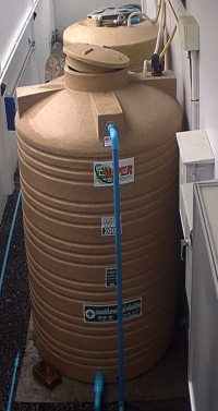
Our water supply here in Thailand comes from a deep well (120m) and is stored in two tanks (1000l + 2000l). There's also a 1000l tank acting as a balance reservoir for the pool. The fill levels of all tanks are controlled by mechanical float switches that turn on the respective pumps as needed. That works reliably most of the time, but a live fill-level display would be genuinely useful — especially once you've already started moving towards a smart home with Home Assistant. A level sensor was needed.
Approach
Ready-made solutions are, as always, quite expensive, and besides, the journey is the destination. I ruled out a mechanical solution from the start to stay maintenance-free. I also didn't want a solution that requires drilling into the tanks below the maximum water level, where sealing could become a problem. Since the tank geometry is known, an ultrasonic distance measurement of the water surface is a good fit. Even during pumping the water surface isn't rough enough to cause significant measurement errors. Examples of DIY solutions can be found here too (some published after my own implementation in 2021):
Since we're dealing with water here, the common, cheap HC-SR04 ultrasonic module is out. But there's a similar, waterproof module: the AJ-SR04M.
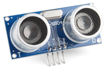
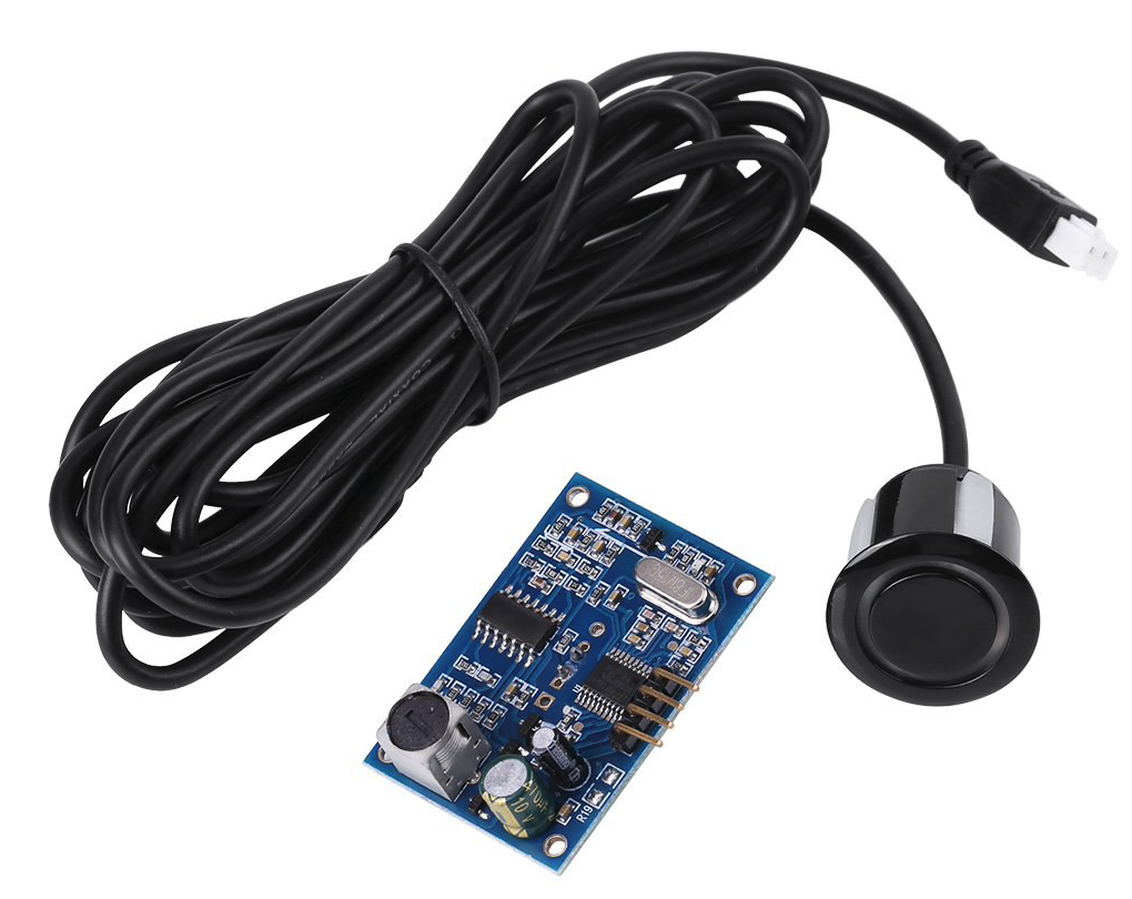
The AJ-SR04M module has a number of nice properties:
- waterproof sensor head
- measuring range from 20cm to 450cm
- good resolution of 0.5cm
- five operating modes (pulse width (default), low power pulse width, automatic serial port, serial port trigger, ASCII code output)
- low standby current draw (<20µA)
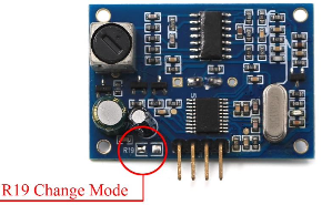
From the HC-SR04 module we know pulse width measurement: to determine distance we measure the time from the trigger signal to the returning echo signal. The AJ-SR04M module has its own onboard microcontroller and performs this timing itself, but can return the result serially. That frees us from time-critical pulse measurements. To put the module into the desired operating mode, resistor R19 needs to be populated correctly:
| Mode | R19 | Standby Current | Low Power Current |
|---|---|---|---|
| 1. Compatible HC-SR04 trigger mode (default) | open | <2mA | - |
| 2. Low Power mode | 300kΩ | <2mA | <40µA |
| 3. Automatic serial port mode | 120kΩ | <2mA | - |
| 4. Low power Serial port mode | 47kΩ | <2mA | <20µA |
| 5. ASCII code output mode | 0kΩ | <2mA | <20µA |
Implementation
I went with mode 4, where a trigger byte is sent over UART serial and the measurement result is then received serially. For that we need a 47KΩ resistor. An 0805 package is intended for R19, but thanks to the large pads a leaded resistor can easily be soldered on too.
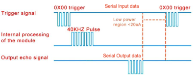
The baud rate is 9600 baud, and after a measurement five bytes are transmitted in the following format:
// AJ_SR04M_Sensor serial format:
// Trigger: 0x00
// Response: Byte1          Byte2  Byte3  Byte4               Byte5
//           Start Byte=FF  MSB    LSB    Checksum (LSB+MSB)  00
The result is in millimeters. Thanks to the serial approach the sensor can now be read out with any PC (via USB-serial adapter) or any controller that has a UART. So far we're only measuring the distance to the water surface. With a bit of math we can convert that distance into liters or a percentage value.
Thanks to Omar Al-Janabi, who already described the calculation in detail. For the calculation we need the tank depth in the direction of measurement, the distance
of the sensor from the highest possible water level (min. 20cm per the sensor spec), the tank capacity
, and of course the measured value
. The formula for centimeters is then:
In my case, as noted below, the following values apply to the water tank:
(x in meters)
The formula could be simplified using the real values, but for clarity I implemented it exactly as shown.
Home Assistant Integration
With an ESP8266 module and ESPHome, integration into Home Assistant is quite straightforward. The serial protocol is most easily handled with a custom component. The following small C program writes the trigger byte on each update request and calculates the measurement result (in meters) from the five received bytes.
- AJ_SR04M_Sensor.h
#include "esphome.h"

class AJ_SR04M_Sensor : public PollingComponent, public UARTDevice, public Sensor {
 public:

  AJ_SR04M_Sensor(UARTComponent *parent) : PollingComponent(5000), UARTDevice(parent) {}

  void update() override {

    char frame[5];
    int pos = 0;
    float value = 0.0;

    write(0x00);
    while (available()) {
      frame[pos] = read();
      pos++;
      if(pos==5) {
        if ((frame[0] == 0xFF) && (frame[4] == 0x00) && ((frame[1]+frame[2])==frame[3])) {
          value = ((frame[1]<<8) + frame[2]) / 1000.0;
          publish_state(value);
        }
        break;
      }
    }
  }
};
In ESPHome we create a new device and add our own code via an includes. The file AJ_SR04M_Sensor.h needs to be copied to /config/esphome.
esphome:
  name: water-level-serial
  comment: "Measure water level of water tanks by ultrasonic wave"
  includes:
    - AJ_SR04M_Sensor.h
Next we add the UART interface. If we don't use pins from a hardware UART, a software UART is automatically implemented. Since I'm connecting a total of 3 modules in my solution, I run out of hardware UARTs anyway.
Finally the sensor implementation. The sensor with ID dist1 provides the measured distance in meters. Using template sensors we can then convert that value into a percentage and a liter value as described above.
uart:
  - id: uart_dist1
    tx_pin: GPIO14
    rx_pin: GPIO12
    baud_rate: 9600

sensor:
  - platform: custom
    lambda: |-
      auto my_sensor = new AJ_SR04M_Sensor(id(uart_dist1));
      App.register_component(my_sensor);
      return {my_sensor};
    sensors:
      unit_of_measurement: m
      accuracy_decimals: 3
      name: "Water Tank Distance"
      id: dist1
  - platform: template
    name: 'Water Tank Level'
    unit_of_measurement: '%'
    accuracy_decimals: 0
    update_interval: 10s
    icon: mdi:water-percent
    lambda: |-
        return (((175-20)-((id(dist1).state*100)-20))/(175-20))*100;
  - platform: template
    name: 'Water Tank Volume'
    unit_of_measurement: 'l'
    icon: mdi:cup-water
    accuracy_decimals: 0
    update_interval: 10s
    lambda: |-
       return (((175-20)-((id(dist1).state*100)-20))/(175-20))*1000;
Mechanics
The sensor head has clip tabs around its edge and is suited for an opening of about 20mm.

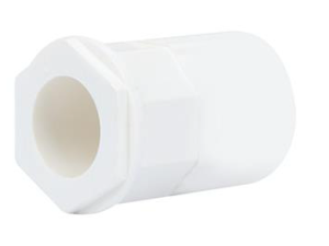
In thin-walled tank housings, a matching conduit connector lets you mount the sensor securely while also sheathing the cable with a cable sleeve.
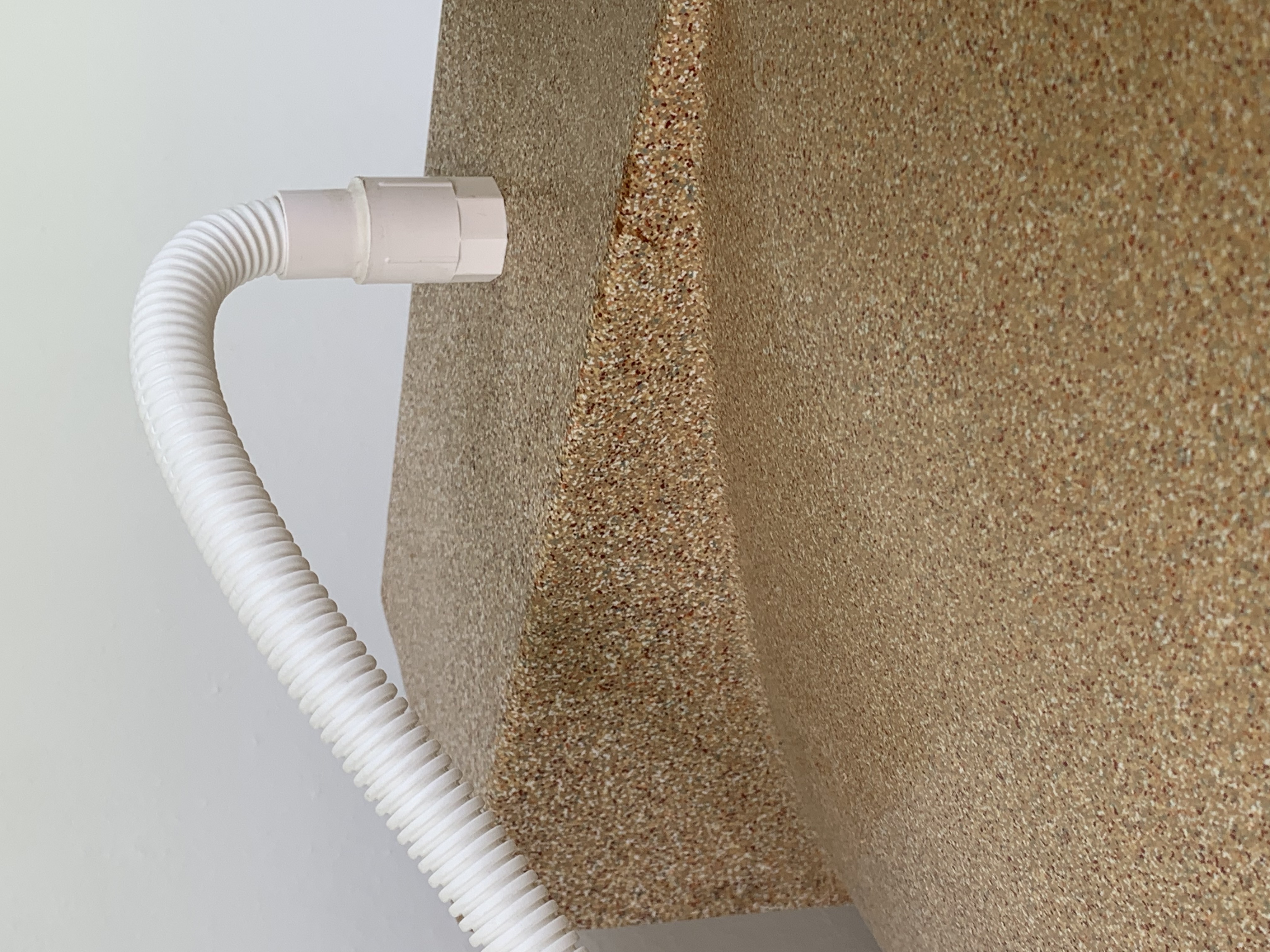
Here's the mounting on top of our well tank. This protects the sensor well against mechanical stress and environmental influences. It has now survived more than a year without a single fault.
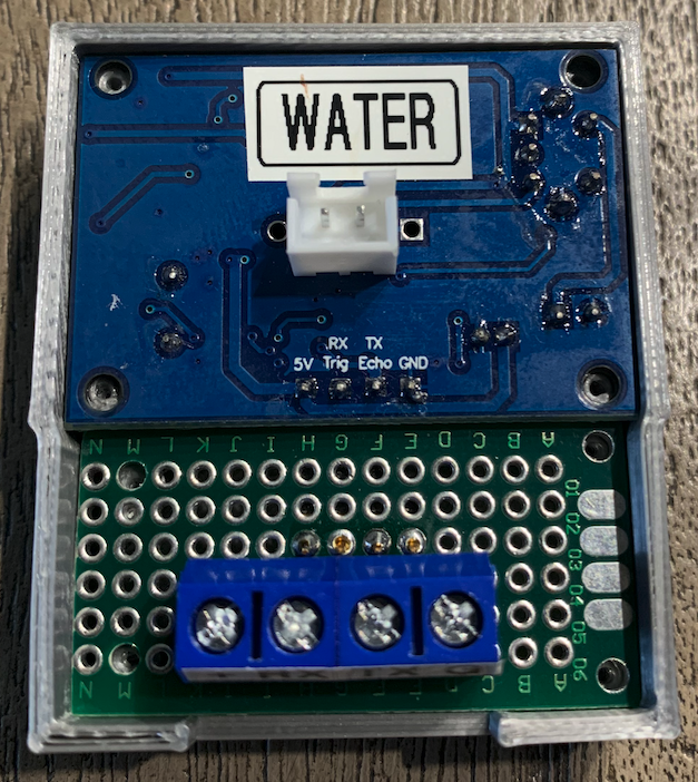
In most cases the 2.5m sensor cable will probably be long enough. In my case, unfortunately, the distance to two of the tanks was greater. Attempts to extend the sensor cable introduced measurement inaccuracies. So instead I moved the AJ control board off the sensor and housed it in a small, waterproof enclosure. The photo only shows the inner 3D-printed housing.
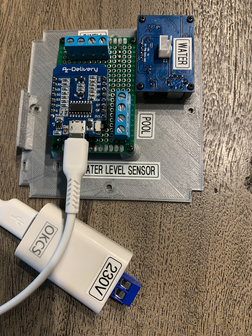
The ESPHome module sits in a somewhat larger, waterproof enclosure. Its internals sit on a 3D-printed carrier. For two water tanks the serial signal arrives at the screw terminals via a 4-wire cable (with the adapter shown above in between), and the closer water tank is connected directly to the measuring module. As a power supply I always use these Apple-like USB power supplies. I've modified the input side to use screw terminals. This solution is quite reliable, very cheap, and safe since it's fully enclosed.
Results
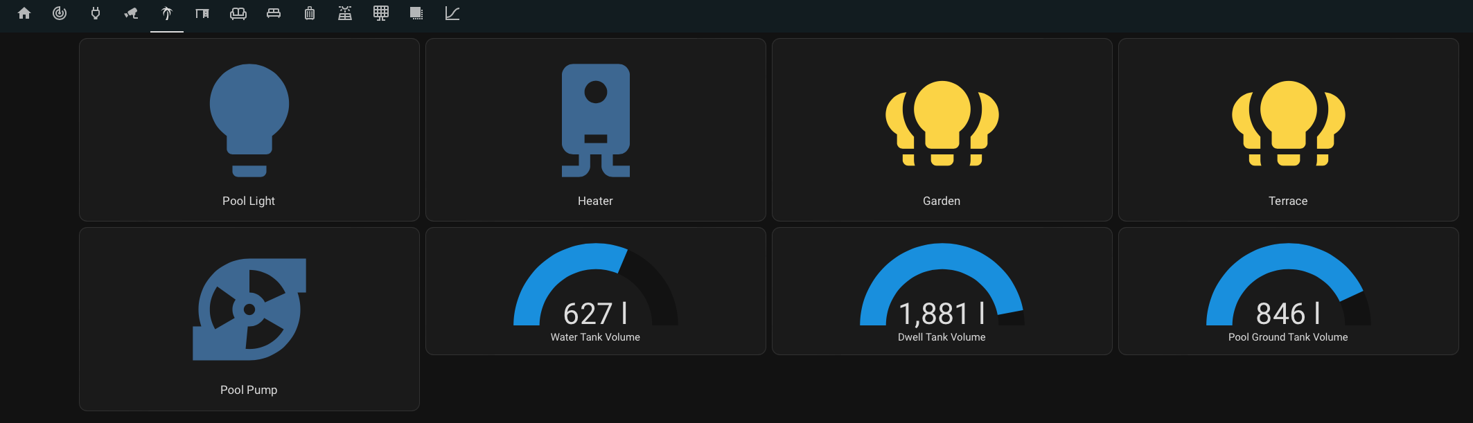
With the work done, the tank fill levels can now be monitored and actions derived from them. Here's a look at the tidy Home Assistant panel for the outdoor area, showing the tank fill levels live.
Of course you can also look at the history:
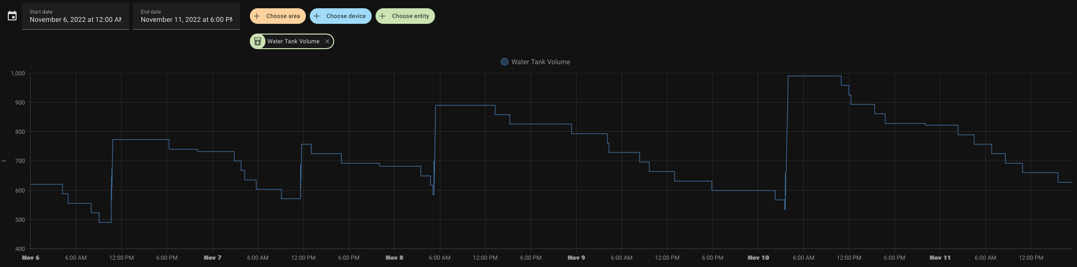
The uneven fill level is due to manual topping-up, since the mechanical limit switch was broken at the time this article was written.
Links
- https://www.home-assistant.io Home Assistant
- https://esphome.io ESPHome
- https://airbnb.com/h/villarollokohsamui You can also come stay with us…
Donate
If you'd like to support my work, feel free to buy me a cappuccino or so: .